Post clear focused pictures of the B1 Korg, showing all wiring.
Also measure the voltage at the other test points, T5, T6, T7, T8 as a start.
Also measure the voltage at the other test points, T5, T6, T7, T8 as a start.
Thanks Ben,
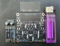
I will test per your instructions this evening. I have some photos here. Excuse the wire length, I wanted to keep them longer during build to accomodate removing the board easily. I'll refit when all is working as it should.

I will test per your instructions this evening. I have some photos here. Excuse the wire length, I wanted to keep them longer during build to accomodate removing the board easily. I'll refit when all is working as it should.
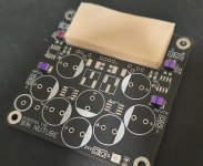
First thing I noticed is that some of the JFETs are oriented wrong. The curved side of the JFET needs to match the curved side of the silkscreened symbol on the PCB. There are three that are incorrect.

I'm seeing that... I didn't even realize! Funny, looking at this picture I posted it is so clear to to see. While working on the board the pieces are so small and its tough to see some of the detail. I need to get a magifying glass for my 3rd hand tool!
I'll correct the JFETs direction.
I'll correct the JFETs direction.
Brijac... it is soldered, you just can't see it from the top. That was one of the hardest bits to solder... so tiny!
I reversed the backwards JFETS, all are correctly oriented now. I took the following measurements:
T1 = 23.8
T2 = 22.9
T3 = 22.0
T4 = 8.9
T5 = 9.0
T6 = 8.9
T7 = 19.5
T8 = 19.5
The adjustment pots have no affect on the voltage for T7 and T8.
I reversed the backwards JFETS, all are correctly oriented now. I took the following measurements:
T1 = 23.8
T2 = 22.9
T3 = 22.0
T4 = 8.9
T5 = 9.0
T6 = 8.9
T7 = 19.5
T8 = 19.5
The adjustment pots have no affect on the voltage for T7 and T8.
I suspect bad solder joints. Looking at the top side of the board there are many solder pads that show no solder between the component lead and the solder pad. That is a sign of either not enough solder or not enough heat applied to the solder at the pad on the bottom the board.
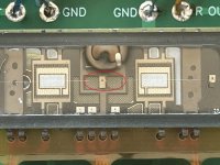
The T5 and T6 voltages indicate that there is no current flowing through the Korg filament.
Have a real close look at the Korg. The filament should be visible as a continuous thin straight wire longitudinally across the tube.
The T5 and T6 voltages indicate that there is no current flowing through the Korg filament.
Have a real close look at the Korg. The filament should be visible as a continuous thin straight wire longitudinally across the tube.
I can see the filament and it is not looking like it is running continuously across the korg? I'll go back through and flow more solder. I learned less is more with solder but I guess you can do too little. Thank you again Ben, really appreciate your time and help!

Last edited:
awesome... will order a replacement. Thanks again Ben!
I'll report back when I have installed the replacement.
I'll report back when I have installed the replacement.
I still think you need to solder the nutube properly (new one). Yes it's not flow trough design of that board, but, if i can see trough the hole then it isn't properly soldered. Try to cover the pad and wire entirely with solder.Brijac... it is soldered, you just can't see it from the top
Last edited:
Another alternative is to use a NuTube socket. That eliminates the possibility of damaging the NuTube through heat and makes it much easier to replace NuTube after failure or defect. Apparently some NuTubes have a limited lifespan.
Pete Millet sells the socket on his EBay website.
Pete Millet sells the socket on his EBay website.
There is no socket for nutube. Those are carrier (decoupling) pcb's. You still need to solder nutube on them. Jazzmaster is using anti vibration mount.
Correct, I have the Millet mount. I'll be sure to cover the entire wire and pad when installing the new nutube.
thanks again!!
thanks again!!
Well, what a surprise for me. I knew about the carrier board but I distinctly remember a socket as well. In fact, there were a number of accessories which are no longer available. I stand corrected, however, if my memory was faulty.
I guess this raises the Q: could individual socket pins be added to the board to permit easy replacement? Offset from board would allow damping sheet to be added between NuTube and PCB.
I guess this raises the Q: could individual socket pins be added to the board to permit easy replacement? Offset from board would allow damping sheet to be added between NuTube and PCB.
Try it and see! Visit the website of Keystone Electronics and study their e-catalog of socket pins. Find candidates that you suspect might work, buy some (Mouser + DigiKey + Newark are authorized distributors), and try them on a B1K PCB in real life. If it works then you have your answer: YES, individual socket pins COULD be added to the board to permit easy replacement.
If none of them work then go through the catalogs of other socket pin manufacturers, who compete against Keystone.
If none of them work then go through the catalogs of other socket pin manufacturers, who compete against Keystone.
You can use pin socket for this, but legs on nutube are so soft, you risk breaking them. There are solutions to decouple, one above pete's with teflon pcb. And i made decouple board to use with wires (which to me should decrease vibration trough conductor even more with properly thin wires). And then use soft sponge (i found makeup sponge to be amazing in light object vibration dampening) with double sided silicone tape. Eva foam combination with it as also good.
Attachments
I am planning to take that approach for biasing resistors and coupling capacitors to permit easy changeout. Planning to use Silclear to ensure good connectivity.Try it and see! Visit the website of Keystone Electronics and study their e-catalog of socket pins. Find candidates that you suspect might work, buy some (Mouser + DigiKey + Newark are authorized distributors), and try them on a B1K PCB in real life. If it works then you have your answer: YES, individual socket pins COULD be added to the board to permit easy replacement.
If none of them work then go through the catalogs of other socket pin manufacturers, who compete against Keystone.
- Home
- Amplifiers
- Pass Labs
- B1 with Korg Triode