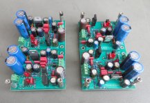
Are you using the UGS Muse board set from Alex (from the group buy). The preamp boards take the +/-24V from the Salas shunt boards laid out by EricD and feeds the +/-24 to the UGS boards. It also reduces the shunt +/-24V voltages to +/-15V for the Muse chips using a pair of TI LDOs. The Jung superregs for the Muse chips would seem to be unnecessary given the way this is done for the UGS Muse preamp?
Turning off the power to the shunts would seem to be a good idea in standby, though they do take a few seconds to come up to voltage when turned on, so that would also need to be accounted for in the muting. I am using a 6 secondary transformer, so powering the main off wouldn't be an option for me; it would need to be the secondary connections or?
Alex: Your UGSD looks really good, I'm glad you found the time to start to finish this! Impressive to say the least!
Thanks Pars. Yes finally I almost finished it and it sounds really good.
Thank you very much Alex 🙂I don’t believe there will be some issues. Just you may need to wait a bit for the UGS to warm up to get the best sound of it. Then for the control, if you need and if I remember well, I believe that I added a couple of unused MCU IO on a spare connector of the control board and I can modify the firmware to control it. Just let me know.
If I have any problems I will let you know.
@Eric06Let me just share the 2 minor issues I experienced when I mounted first time the rear panel (was for an UGS all inclusive so almost 10 years ago !).
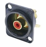
a) The holes for the RCA connectors were a little too big for the REAN/Neutrik version of the BOM. If using these, you need 10mm diameter instead of 11.5mm as currently drawn.
b) The DB15 opening was slightly too small in the direction of the fixing holes so end up having to slightly file the cut-out to enlarge it.
If it can help, I just tentatively corrected these 2 points in this attached version.
Remark: for the DB15, I used the standard macro provided by the front designer tool with adding 2 blind holes 2mm deep, 6mm diameter on top of the fixing holes. This is to compensate for the 3mm thickness of the panel when using hex jack screw terminals.
@Alex_twn
Hi Eric (or Alex; not sure if Eric is still on here or not),
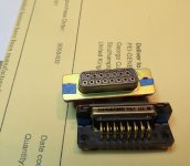
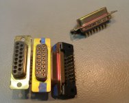
Stupid question re: the DB15 connectors: the way the rear panel is done in FrontPanelExpress, it appears that the screw locks for the connector were supposed to be removable in order to rear mount the connector and fasten it in place. None of the recommended DB15 part numbers are done this way. The screwlocks are fixed to the connector. The ones I have which I looked at are the TE 3-338169-2 (Logic supply) and the Amphenol ID15S33E4GV00LF for Eric's PSU board. I've been digging thru datasheets some today and am not clearly seeing any with removable screwlocks. Did they quit making these? I remember back in the day using external drives with DB SCSI cables on them and getting irritated at the time when the screwlocks would come out with the cable 🙁
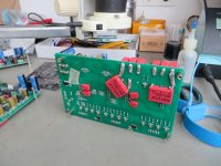
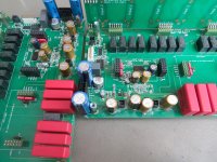
Here are a few words about my implementation.
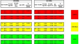
This project was frozen for years and now I started working on it. I want to share that I paid special attention to the UGS modules. Extremely matched original 2SK389BL and 2SJ109BL. 10 years ago I bought about 50 of each type. Original, verified. I selected the best quads for my projects (UGS MUSE, XA60.8) and sold off the rest. A lot of members here have bought from me.
ZTX450 and ZTX550 are also matched (hfe). And all resistors are 0.1%.
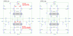
The photos of the UGS modules show the very small disbalance in the trimmers (adjusted modules). Maybe I'll replace them with fixed resistors. The use of 10 ohm trimmers required a small change to some resistors (given in red).
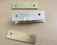
There was a little milling of the radiators due to the difference in the thicknesses of the jfets and ZTX (0.2mm). Arctic TP-3 thermal pad (thickness 0.5mm) was used.
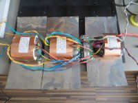
About the main power supply. It will probably also be used for a DAC and/or phono preamp (additional output connectors). R-core transformers. Additional permalloy tape magnetic shield. The capacitors are Keindel 22000uF/50V. Diodes - HFA04TB60. Drossel: CH-1 Signal Transformer 100mH, DC resistance 1R5. RCLC filter (1R0 - 22000uF - 100mH/1R5 - 22000uF. Piezo switch on the front panel.
Attachments
-
 jfet_milling.jpg697.3 KB · Views: 180
 -
 jung_regulators_for_muses72320.jpg799.2 KB · Views: 199
 -
 jfets_measurement.jpg134.4 KB · Views: 180
 -
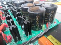 kendeil_22000uf.jpg796.7 KB · Views: 172
 -
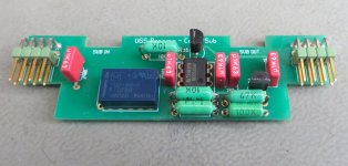 low_noise_resistors.jpg447.4 KB · Views: 179
 -
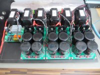 main_psu.jpg823.3 KB · Views: 178
 -
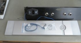 panels_psu.jpg433.1 KB · Views: 190
 -
 preamp_back.jpg671.3 KB · Views: 178
 -
 preamps1.jpg869.2 KB · Views: 194
 -
 rcore.jpg667 KB · Views: 230
 -
 UGS_V3a-(my).gif33.8 KB · Views: 248
 -
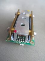 ugs1.jpg511.5 KB · Views: 226
 -
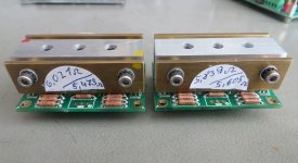 ugs2.jpg495 KB · Views: 174
 -
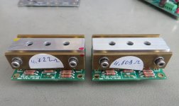 ugs3.jpg494.1 KB · Views: 178
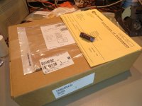
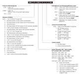
Thanks for that! Those ITT db15s are expensive. I was going thru the datasheet trying to find what I think I am looking for. Your part number, DAMM15PDA101, gives a straight, solder cup part with holes where the screw jack goes. Looking at the datasheet, it would appear that the hardware modifier G, 90 degree bracket, threaded 4-40 fastener and jack screw, with board locks would be what I would want, but finding one seems to be a problem. M3 threading would be fine with me as well, but guessing here in the US most if not all DB15 cables would use 4-40 and not metric M3.
At Mouser, I can find an ITT DAMG15SJA197 for a female. No G models in stock. Digikey shows either a DAMG15PPK87 or DAMG15PRK87 available thru their marketplace. All at ~$30 apiece.
I found a place called Winford Engineering in Michigan which seems to make what I am looking for, in their CNR15F-XF-CJF-RC and CNR15M-XF-CJF-RC, so I went ahead and ordered some.
Sometimes the simplest parts become the biggest PITA to find the correct ones.
Attachments
Very nice job ! I saw that you made a couple of fine tuning to the original design. Good idea. If I had to design this one again I will also do some non critical little adjustments.Here are a few words about my implementation.
This project was frozen for years and now I started working on it. I want to share that I paid special attention to the UGS modules. Extremely matched original 2SK389BL and 2SJ109BL. 10 years ago I bought about 50 of each type. Original, verified. I selected the best quads for my projects (UGS MUSE, XA60.8) and sold off the rest. A lot of members here have bought from me.
ZTX450 and ZTX550 are also matched (hfe). And all resistors are 0.1%.
The photos of the UGS modules show the very small disbalance in the trimmers (adjusted modules). Maybe I'll replace them with fixed resistors. The use of 10 ohm trimmers required a small change to some resistors (given in red).
There was a little milling of the radiators due to the difference in the thicknesses of the jfets and ZTX (0.2mm). Arctic TP-3 thermal pad (thickness 0.5mm) was used.
About the main power supply. It will probably also be used for a DAC and/or phono preamp (additional output connectors). R-core transformers. Additional permalloy tape magnetic shield. The capacitors are Keindel 22000uF/50V. Diodes - HFA04TB60. Drossel: CH-1 Signal Transformer 100mH, DC resistance 1R5. RCLC filter (1R0 - 22000uF - 100mH/1R5 - 22000uF. Piezo switch on the front panel.
I made those on the UGSD so I am not spending too much time on the UGS muse.
The analog portion of the UGSD is very similar to the one of the UGS muse with minor adjustments.
I think that I can easily find those in my local electronic shop so if you need I can buy some for you and ship them. Those are usually very cheap.Thanks for that! Those ITT db15s are expensive. I was going thru the datasheet trying to find what I think I am looking for. Your part number, DAMM15PDA101, gives a straight, solder cup part with holes where the screw jack goes. Looking at the datasheet, it would appear that the hardware modifier G, 90 degree bracket, threaded 4-40 fastener and jack screw, with board locks would be what I would want, but finding one seems to be a problem. M3 threading would be fine with me as well, but guessing here in the US most if not all DB15 cables would use 4-40 and not metric M3.
At Mouser, I can find an ITT DAMG15SJA197 for a female. No G models in stock. Digikey shows either a DAMG15PPK87 or DAMG15PRK87 available thru their marketplace. All at ~$30 apiece.
I found a place called Winford Engineering in Michigan which seems to make what I am looking for, in their CNR15F-XF-CJF-RC and CNR15M-XF-CJF-RC, so I went ahead and ordered some.
Sometimes the simplest parts become the biggest PITA to find the correct ones.
I follow with interest UGSD.
Thank you Alex and Eric for all the effort you've put in these projects and we're use it.
Thank you Alex and Eric for all the effort you've put in these projects and we're use it.
I have a few questions about a trigger board.
When coming input signal on IN1, IN2, IN3, IN4 or waking up from standby (power on) I want to power on my Salas UBiBs for UGS modules (4 relays).
Accordingly, when the input signal drops out or standby on --> power off UBiBs.
Can I get a signal to control relays from trigger out Left Amp or trigger out Head Amp?
Or from TRIGGER_LATCH (U12 pin 14, 74HC259, uP board)?
What is happening with these output when coming signal to IN1-4 or power on preamp.
Is there always an pulse (in pulse mode) under these conditions?
And what is the pulse duration?
For a latching relay I need a pulse greater than 30ms.
If it is short I have to use a monostable multivibrator to form a longer pulse.
What size of standoffs are required for the preamp boards? 10mm appears to be too tall (using all metric, so M3 standoffs).
I use 10mm because on the underside of the boards I have soldered additional 10uf film capacitors thick 8mm.
My comment regarding standoff size was based on test fitting a prototype Face_Arriere_Maousse_mod.fpd Front Panel express rear panel to one of the I/O boards plugged into a preamp board. The XLRs are spaced 26.5mm from the bottom of the panel (i.e., the floor of the enclosure). A 10mm standoff appears to be too high, but I need to mount the XLRs to the proto panel and recheck.
Thanks for the input!
Thanks for the input!
That layout looks like it would have clearance issues with the side panels of a Modushop Slim Line enclosure. What upper output jacks are those (look like XLR but a bit smaller)?
NF2D-B-2 and NF2D-B-9What upper output jacks are those (look like XLR but a bit smaller)?
My enclosure width is 410mm. Only front panel is 430mm.
Attachments
Last edited:
Just an FYI. I searched thru the UGS All Inclusive thread on homecinema.fr and found that an M3 x 5mm spacer is what is used for the preamp boards to the case bottom if using the FPE file done by Maouse (sp?) with the XLRs spaced at 26.5mm from the case bottom. I have some 6mm so will try those, and order 5mm if required.
Not speaking French, the homecinema search function won't search by English words, so had to reverse engineer the French word for spacer (entretoises).
Not speaking French, the homecinema search function won't search by English words, so had to reverse engineer the French word for spacer (entretoises).
I can check this next week when I am back home as I am traveling at the moment.I have a few questions about a trigger board.
When coming input signal on IN1, IN2, IN3, IN4 or waking up from standby (power on) I want to power on my Salas UBiBs for UGS modules (4 relays).
Accordingly, when the input signal drops out or standby on --> power off UBiBs.
Can I get a signal to control relays from trigger out Left Amp or trigger out Head Amp?
Or from TRIGGER_LATCH (U12 pin 14, 74HC259, uP board)?
What is happening with these output when coming signal to IN1-4 or power on preamp.
Is there always an pulse (in pulse mode) under these conditions?
And what is the pulse duration?
For a latching relay I need a pulse greater than 30ms.
If it is short I have to use a monostable multivibrator to form a longer pulse.
But as I remember, as the trigger part is fully reused from the original UGS AI, the IN1 to IN4 are actually trigger outputs to control the audio gears you will plug on input 1 to input 4 of the UGS Muse.
There is anyway an input on the trigger to monitor the state of the connected audio gear so we can reuse this input and probably modify it as you wish, this is just software and easy to adjust.
I need to check carefully when I am back, please remind it to me if I don’t get back to you.
I also can adjust the pulse size.
- Home
- Amplifiers
- Pass Labs
- UGS-muse preamp GB
