correction:
you can use SE AVC in context of Iron Pre Bal, in two possible scenarios, both of these enabling deleting of regular resistive attenuator, both of these dictating output autoformer in place
1. if strictly using SE inputs, AVC preceding output autoformer; in that scenario even neg leg buffer isn't needed; AVC connected in normal way, top tap fed from positive buffer, selected tap going to positive tap of output autoformer, bottom tap going to GND
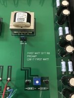
What do we know about the original B1T?
If the buffer a pair of 2SK/2SJ?
Is the pot there to adjust DC-offset like on Iron Pre. Do we know the value (depends of how "tight" the pair is matched?)?
The two resistors:
If the wide brown band at the left is the tolerance (1%) then the left resistor is a very large value and it goes to the ground plane of PCB.
Is that resistor connected to the wiper of the pot to ensure a reference to ground even if "wiper slips"?
Then the resistor to the right is the gate resistor?
Attachments
Sorry that I couldn't post well,
I didn't understand using se AVC in Bal PCB.
AVC instead of cinemag,
Top tap-E-5
Select tap-out+
Bottom tap-GND out
Then only RCA output?
Or using cinemag and AVC is set before cinemag?
I didn't understand using se AVC in Bal PCB.
AVC instead of cinemag,
Top tap-E-5
Select tap-out+
Bottom tap-GND out
Then only RCA output?
Or using cinemag and AVC is set before cinemag?
What do we know about the original B1T?
we know everything
pretty much B1 R.2 (complementary JFet buffer) and logic sez - no (idiotproof part) 1K in series with buffer output
Sorry that I couldn't post well,
I didn't understand using se AVC in Bal PCB.
Tamra, for that you need to check Iron Pumpkin thread, starting from post #4 and then several following
Note - I didn't advised using SE AVC in Balanced Iron Pre; I was saying and repeating - take care of finding proper Balanced AVC for implementation iin Iron Pre (Bal)
Anyway, principle is here ( both SE and Bal); ignore "Diamond" for buffer - it was used in development and as soon I realized that there are current produced Toshiba JFets (in smd), further steps included those


I have the Lazy Bush mono blocks so IP-BAL mono blocks will be placed close to those (connected using short RCA cables).
I need to find out how to place IP-BAL close to LB as this determines the length of XLR cable from DAC (placed in the center) to IP-BAL.
It will be 1m at least.......probably a little bit longer which I think is ok for an XLR cable.
I need to find out how to place IP-BAL close to LB as this determines the length of XLR cable from DAC (placed in the center) to IP-BAL.
It will be 1m at least.......probably a little bit longer which I think is ok for an XLR cable.
Yes, the Lazy Bush implementation is with remote SMPS that it kept away via wire. Inside LB there is a 5A DC filter choke + large cap.
I use 1.3m speaker cable in the moment from LB to speaker and this is already a bit too long with current placement of LB. I wonder if it will be worth to maybe reduce length to 0.5m or shorter speaker wire. If I optimize placement speaker cable could be even shorter but then XLR cable will probably be a bit longer as I still want short RCA cable from IP-BAL to LB.
I use 1.3m speaker cable in the moment from LB to speaker and this is already a bit too long with current placement of LB. I wonder if it will be worth to maybe reduce length to 0.5m or shorter speaker wire. If I optimize placement speaker cable could be even shorter but then XLR cable will probably be a bit longer as I still want short RCA cable from IP-BAL to LB.
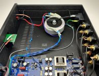
Sneak preview 🎥


There's not really too much to say about this build, things are extremely straightforward, it works great, and as the other builders already know, it sounds absolutely fantastic!
A few notes before people ask -
I didn't use a remote volume shaft as I didn't have one. Use one of you want, it's a great idea. The wires from PCB to the volume pot are mic cable, and it's wonderfully quiet.
I used a fused and switched IEC. It makes the wiring so much simpler.
In North American wiring convention black is Live (as that's what color it will turn your finger if you touch it), white is Neutral, green is Earth/Ground. Please note the heat shrink on the IEC, and also that the IEC has L and N labeled. (hard to see in these photos).
Live is sent to the front panel switch (which is AC rated, of course) and then to the lead windings of the transformer primary, which being an Antek happen to be red. The trail winding of the primary attaches directly to neutral. These winding leads are unfortunately black, but oh well.
Safety Earth/Ground is bolted directly to chassis through the green wire.
If it's not immediately obvious, the grey wire is connected from the pad on the PCB marked "Chassis" to the chassis earth.
The power on/off LED steals power from the pads on the PCB, and has an inline resistor under the heatshrink. I used a blue, and about 33K as modern LED are amazingly bright.
Cable from the PCB to Volume is Canare L-282AT https://www.redco.com/Canare-L-2B2AT.html
The little PCB on the Alps volume pot isn't necessary, but it sure does make things easy to solder.
The rest of the signal wiring is Mogami 2330 https://www.redco.com/Mogami-W2330.html
No idea where I got the knobs... probably Amazon, I had a bunch in my box and these looked pretty cool.
Attachments
Last edited:


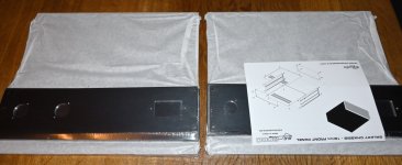
Well, the circuit board and associated parts will arrive tomorrow, so I just have to say that after even seeing the front panel, the decision is made for me to move forward asap with the project. FUGLY, yes, very good.
You're not a 'mere' human... you're a special human. Read the big bold red stuff at the top of post #1. They've been available to people just like yourself for a number of weeks.Guess us mere humans will have to wait for any dribblings to appear in the Store..🙁
Cheers
Oh drats & such.....no SE versions available..I shall wait patiently and read through these 115 pages to learn the fugly language, or the language of the Fugly, so I can be prepared...
- Home
- Amplifiers
- Pass Labs
- Iron Pre Essentials Kits For The DIYA Store - Register Your Interest