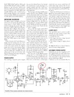
The architecture of X-Altra and LP797 MM preamp lightly resembles my PBamp-86 ["Radio Yearbook-86", p. 51 - I am attaching it below], only instead of a bipolar at the input, and the rest an input with a common source, then inverting the op-amp and a common frequency-setting NFB loop from the output of the op-amp to the source of the input transistor, almost like mine. Except for the needlessly stuffed thick capacitor C90 between the input stage and the op-amp.
What's in the negative? Andrew set the LSK389 mode with a drain current of 1.5 mA, and this is 3-4 times less than the current of the optimal mode, in which such fet has the minimal noise [see p. 68 of my book "Technique of high-quality sound reproduction", 1985 , I officially distribute it here https://www.patreon.com/posts/67628599 , and See also Fig.6-16 of JFE2140 datasheet]. We lose a few dB stupidly from scratch, and in addition, by the non-solder R80, to which R79 and R81 are also paralleled, we judge that Andrew does not suspect that the optimal input impedance can be much higher than the "standard" 47 kOhm [ https://patreon.com/posts/70415214 ].
The negative of the circuit design of the input stage is also its high sensitivity to supply voltage ripples. As the author himself notes on page 57 in the third paragraph from the bottom of the left column, PSRR is 0 dB, i.e. the power supply ripples are transmitted to the output of the input stage without attenuation! In order to prevent catastrophic deterioration of the SNR by the power supply, Andrew was forced to build a special active smoothing filter for powering the input stage on the second half of the U26 + R78 + C88 op-amp (at 1000 uF!), and for each channel its own.
I note that in Cy-XXI the two mentioned problems are practically absent due to the fact that in its architecture the first two stages are differential. That is, the noise of the current generator T1 also of course passes to the drains (outputs) of both input transistors FET1.1 FET1.2, but they are common-mode and therefore almost completely compensated as an input common-mode voltage by the second differential pair T2 and T3. For the same reason, interference from the supply voltage buses is also compensated. Those interested can familiarize themselves with the mathematics of processes in detail on pages 71-74 of my book www.patreon.com/posts/67628599 or by googling CMRR, PSRR.
Finishing with X-Altra MM corrector circuitry, let's calculate the number of separating capacitors: C90 + C82 (electrolyte) + C73 + C72 + C61 (electrolyte) = 5 in total, of which 2 are electrolytic. Too many, imho.
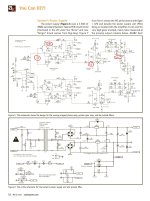
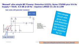
Let's move on to MC preamplifier. MC carts are fundamentally different from MM not only by an order of magnitude lower than the nominal EMF (at one kilohertz, typically 0.4 mV versus 5 mV), but also by two orders lower coil resistance (typically 12 Ohm versus 1 kOhm) and by 4 orders lower inductance (typically 75 uH versus 0.5 H). This is actually the lowest impedance and low level audio signal source. Russell for the MC preamplifier applied the recently fashionable complementary pair topology with a common base [ if the sclerosis correctly changes me, proposed at the end of the last century by Marshall Leach, https://leachlegacy.ece.gatech.edu/headamp/ ] on the mystery-covered "magic" bipolar transistors ZTX851/ZTX951.
The main design headache in this stage is preventing the ZTX851/951 from flowing significant input mismatch emitter current through the MC cartridge. In contrast to the huge 5000 uF input isolation electrolyte (see Moving coil headamps rev.2, Maxwell version, [ https://hifisonix.com/technical/mc-head-amp-circuit-compendium/ ] ), the floating supply from a 1.5-volt battery (Hawking and Planck) or the unthinkable selection of transistors with a base-emitter voltage difference of no more than 1 mV (Weinberg), Russell originally applied a DC servo on the OpAmp U1, approximately the same as in my Cy-XXI from version 4 and higher. Those, through the resistor R1 monitors the DC at the input and feeds it to the integrator comparator U1, from the output of which through R35R36 controls the base bias Q1Q2 so that the DC input is zero with an error of no more than zero bias voltage U1 OpAmp OPA2188, i.e. +-6 uV. For reference, I used OPA192 in DC servo, which has a +-5 uV offset, but it is better than OPA2188 in the sense that it is made using silent eTrim technology, unlike the 2188 chopper (interrupter), whose modulator / demodulator buzzes at several tens or hundreds of kilohertz, adding sticks to the input currents of the op-amp.
It’s clear with DCservo, but what else is done in Russell’s circuit for a pair of op-amps U3, U4 in each channel? And these are active smoothing filters for the collector circuits of these same ZTX851 / ZTX951. And with a bunch of thick electrolytes C17C18C9C10. And in addition, another 2x1000 microfarads in the separating conduits C11, C16. After all, this circuit is just as helpless against power ripples as the MM part of the Russell corrector, PSRR = 0 dB (second from the bottom paragraph of the left column on page 65 of AXpress February 2021). In terms of the number and capacity of electrolytes, this micropower MC preamplifier with a linear frequency response and a gain of 20 dB bypasses the 100-watt PowAmp on the TDA7294, such a construction is so big that makes it imposisble moutning neither inside tonearm nor even inside turntable.
But for the sake of fairness, we must admit that the scheme of his MC-preamplifier is interesting, because before him no one used DCservo @ input.
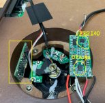
But in fairness, it should be noted that the circuitry of the Cy-XXI phonopreamp, with much less complexity and simply drastically smaller dimensions 20х45х3 мм [ https://www.patreon.com/posts/insaidnyi-ot-vip-72574505 ], provides a level 553 nV/root Hz or 75 nV at 20 kHz or 74 dBA with respect to the standard 0.4 mV for a 12 Ohms head. Those almost the same noise as the trendy ZTX851/ZTX951 pair, but without the problems with thick electrolytes and power distillation and easily and trouble-free mounted in the optimal place - in the basement of the conclusions directly to the tonearm inside the turntable.
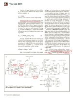
By the way, the author Dennis Colin, mentioned by Andrew Russell, from whom Andrew borrowed the architecture of the MM phonopreamp, formed his MC phono from the MM phono in the same way that I formed the Su-XXI_v.8_MС from v.7_MM: he simply added 20 dB amplification, and did not bathe with any additional preamps. As a prooflink, see the article by D. Colin from AudioXpress 2007, where on page 3 and Figure 2 you will find that trivial S1A, which is equivalent to replacing the 180 Ohm resistor in the Su-XXI_v.7_MM circuit with an 18 Ohm resistor in Su -XXI_v.8_MC. In conclusion, on page 2 of his article, note how much hassle was with the suppression of excitations of the op-amp. And add that Cy-XXI has 5 times less than "LP 797 Ultra-Low Distortion Phono Preamp". Can someone tell me how to call 5 times smaller than "ultra-small" ? 🙂
Conclusions. Vivat phonocore Cy-XXI 🙂) , no noise, no excitations, no distortion and no electrolytes, right? 🙂
Regards, Nick Sukhov
PS.
More detailed and illustrated info is here:
https://www.patreon.com/posts/pros-and-cons-mm-87586740
https://www.patreon.com/posts/skhema-gerbery-i-86997687
I remind you that in my phonopreamp it is exclusive in relation to the vast majority of others:
-minimum input capacitance 13...25 pF (depending on the version) with an input resistance of 150
kOhm; thanks to this, budget MM heads sound subjectively like top-end MCs.
-the original T-circuit of the frequency-setting negative feedback through R12C4 forms the time
constant tau4 ("7950 us" Amendment No. 4 to 'Processed Disk Records and Reproducing Equipment'
IEC 60098), and R10C3 provides aperiodic RF correction (a kind of "Neumann pole" compensator
"). Due to this, infrasonic interference is effectively suppressed, and the transparency of highfrequency
sounds is also ensured.
For reference: tau1 = 75 us is formed by the R9C3 chain, tau 2 = 318 us - by the R9R12C5 chain, tau3 =
3180 us - by the R11C5 chain.
-active current generator T1, coupled with the first FET1.1 FET1.2 and the second T2 T3 differential
stages provide good noise suppression from the power rails, preventing the need for overthorough
distillation.
-the second differential stage T2 T3 suppresses the fluctuation noise of the current generator T1 as a common mode
signal, minimizing the noise of the input stage.
-along the entire path of the sound signal, there are no electrolytic and generally separating capacitors at all.
-connection of the general feedback circuit to the output stage with a large output impedance ensures the constant
loop gain over the entire audio frequency range and thereby maximizes the overload capacity and minimizes the nonlinear
distortions as in the LF as well as on HF.
The numbering of the elements is according to the Cy-XXI_v.7 circuit and PCB gerbers for MM, from here: [ https://www.patreon.com/posts/skhema-gerbery-i-86997687 ]
What's in the negative? Andrew set the LSK389 mode with a drain current of 1.5 mA, and this is 3-4 times less than the current of the optimal mode, in which such fet has the minimal noise [see p. 68 of my book "Technique of high-quality sound reproduction", 1985 , I officially distribute it here https://www.patreon.com/posts/67628599 , and See also Fig.6-16 of JFE2140 datasheet]. We lose a few dB stupidly from scratch, and in addition, by the non-solder R80, to which R79 and R81 are also paralleled, we judge that Andrew does not suspect that the optimal input impedance can be much higher than the "standard" 47 kOhm [ https://patreon.com/posts/70415214 ].
The negative of the circuit design of the input stage is also its high sensitivity to supply voltage ripples. As the author himself notes on page 57 in the third paragraph from the bottom of the left column, PSRR is 0 dB, i.e. the power supply ripples are transmitted to the output of the input stage without attenuation! In order to prevent catastrophic deterioration of the SNR by the power supply, Andrew was forced to build a special active smoothing filter for powering the input stage on the second half of the U26 + R78 + C88 op-amp (at 1000 uF!), and for each channel its own.
I note that in Cy-XXI the two mentioned problems are practically absent due to the fact that in its architecture the first two stages are differential. That is, the noise of the current generator T1 also of course passes to the drains (outputs) of both input transistors FET1.1 FET1.2, but they are common-mode and therefore almost completely compensated as an input common-mode voltage by the second differential pair T2 and T3. For the same reason, interference from the supply voltage buses is also compensated. Those interested can familiarize themselves with the mathematics of processes in detail on pages 71-74 of my book www.patreon.com/posts/67628599 or by googling CMRR, PSRR.
Finishing with X-Altra MM corrector circuitry, let's calculate the number of separating capacitors: C90 + C82 (electrolyte) + C73 + C72 + C61 (electrolyte) = 5 in total, of which 2 are electrolytic. Too many, imho.
Let's move on to MC preamplifier. MC carts are fundamentally different from MM not only by an order of magnitude lower than the nominal EMF (at one kilohertz, typically 0.4 mV versus 5 mV), but also by two orders lower coil resistance (typically 12 Ohm versus 1 kOhm) and by 4 orders lower inductance (typically 75 uH versus 0.5 H). This is actually the lowest impedance and low level audio signal source. Russell for the MC preamplifier applied the recently fashionable complementary pair topology with a common base [ if the sclerosis correctly changes me, proposed at the end of the last century by Marshall Leach, https://leachlegacy.ece.gatech.edu/headamp/ ] on the mystery-covered "magic" bipolar transistors ZTX851/ZTX951.
The main design headache in this stage is preventing the ZTX851/951 from flowing significant input mismatch emitter current through the MC cartridge. In contrast to the huge 5000 uF input isolation electrolyte (see Moving coil headamps rev.2, Maxwell version, [ https://hifisonix.com/technical/mc-head-amp-circuit-compendium/ ] ), the floating supply from a 1.5-volt battery (Hawking and Planck) or the unthinkable selection of transistors with a base-emitter voltage difference of no more than 1 mV (Weinberg), Russell originally applied a DC servo on the OpAmp U1, approximately the same as in my Cy-XXI from version 4 and higher. Those, through the resistor R1 monitors the DC at the input and feeds it to the integrator comparator U1, from the output of which through R35R36 controls the base bias Q1Q2 so that the DC input is zero with an error of no more than zero bias voltage U1 OpAmp OPA2188, i.e. +-6 uV. For reference, I used OPA192 in DC servo, which has a +-5 uV offset, but it is better than OPA2188 in the sense that it is made using silent eTrim technology, unlike the 2188 chopper (interrupter), whose modulator / demodulator buzzes at several tens or hundreds of kilohertz, adding sticks to the input currents of the op-amp.
It’s clear with DCservo, but what else is done in Russell’s circuit for a pair of op-amps U3, U4 in each channel? And these are active smoothing filters for the collector circuits of these same ZTX851 / ZTX951. And with a bunch of thick electrolytes C17C18C9C10. And in addition, another 2x1000 microfarads in the separating conduits C11, C16. After all, this circuit is just as helpless against power ripples as the MM part of the Russell corrector, PSRR = 0 dB (second from the bottom paragraph of the left column on page 65 of AXpress February 2021). In terms of the number and capacity of electrolytes, this micropower MC preamplifier with a linear frequency response and a gain of 20 dB bypasses the 100-watt PowAmp on the TDA7294, such a construction is so big that makes it imposisble moutning neither inside tonearm nor even inside turntable.
But for the sake of fairness, we must admit that the scheme of his MC-preamplifier is interesting, because before him no one used DCservo @ input.
But in fairness, it should be noted that the circuitry of the Cy-XXI phonopreamp, with much less complexity and simply drastically smaller dimensions 20х45х3 мм [ https://www.patreon.com/posts/insaidnyi-ot-vip-72574505 ], provides a level 553 nV/root Hz or 75 nV at 20 kHz or 74 dBA with respect to the standard 0.4 mV for a 12 Ohms head. Those almost the same noise as the trendy ZTX851/ZTX951 pair, but without the problems with thick electrolytes and power distillation and easily and trouble-free mounted in the optimal place - in the basement of the conclusions directly to the tonearm inside the turntable.
By the way, the author Dennis Colin, mentioned by Andrew Russell, from whom Andrew borrowed the architecture of the MM phonopreamp, formed his MC phono from the MM phono in the same way that I formed the Su-XXI_v.8_MС from v.7_MM: he simply added 20 dB amplification, and did not bathe with any additional preamps. As a prooflink, see the article by D. Colin from AudioXpress 2007, where on page 3 and Figure 2 you will find that trivial S1A, which is equivalent to replacing the 180 Ohm resistor in the Su-XXI_v.7_MM circuit with an 18 Ohm resistor in Su -XXI_v.8_MC. In conclusion, on page 2 of his article, note how much hassle was with the suppression of excitations of the op-amp. And add that Cy-XXI has 5 times less than "LP 797 Ultra-Low Distortion Phono Preamp". Can someone tell me how to call 5 times smaller than "ultra-small" ? 🙂
Conclusions. Vivat phonocore Cy-XXI 🙂) , no noise, no excitations, no distortion and no electrolytes, right? 🙂
Regards, Nick Sukhov
PS.
More detailed and illustrated info is here:
https://www.patreon.com/posts/pros-and-cons-mm-87586740
https://www.patreon.com/posts/skhema-gerbery-i-86997687
I remind you that in my phonopreamp it is exclusive in relation to the vast majority of others:
-minimum input capacitance 13...25 pF (depending on the version) with an input resistance of 150
kOhm; thanks to this, budget MM heads sound subjectively like top-end MCs.
-the original T-circuit of the frequency-setting negative feedback through R12C4 forms the time
constant tau4 ("7950 us" Amendment No. 4 to 'Processed Disk Records and Reproducing Equipment'
IEC 60098), and R10C3 provides aperiodic RF correction (a kind of "Neumann pole" compensator
"). Due to this, infrasonic interference is effectively suppressed, and the transparency of highfrequency
sounds is also ensured.
For reference: tau1 = 75 us is formed by the R9C3 chain, tau 2 = 318 us - by the R9R12C5 chain, tau3 =
3180 us - by the R11C5 chain.
-active current generator T1, coupled with the first FET1.1 FET1.2 and the second T2 T3 differential
stages provide good noise suppression from the power rails, preventing the need for overthorough
distillation.
-the second differential stage T2 T3 suppresses the fluctuation noise of the current generator T1 as a common mode
signal, minimizing the noise of the input stage.
-along the entire path of the sound signal, there are no electrolytic and generally separating capacitors at all.
-connection of the general feedback circuit to the output stage with a large output impedance ensures the constant
loop gain over the entire audio frequency range and thereby maximizes the overload capacity and minimizes the nonlinear
distortions as in the LF as well as on HF.
The numbering of the elements is according to the Cy-XXI_v.7 circuit and PCB gerbers for MM, from here: [ https://www.patreon.com/posts/skhema-gerbery-i-86997687 ]
Attachments
-
 SukhovPBAmp-Radioyearbook86_page51.png331.5 KB · Views: 745
 -
 Colin LP 797_page_3.jpg579.1 KB · Views: 826
 -
 AX-Mar2021-ARussellXAltraP2_page58.jpg343.5 KB · Views: 820
 -
 AX-Feb2021-ARussellXAltra_page64.jpg430.3 KB · Views: 799
 -
 Moving-coil-head-amps-rev-2_Maxwell.jpg234.3 KB · Views: 747
 -
 ztxElectrolytes.jpg563.6 KB · Views: 703
 -
 cyXXIinsidemontage.png715.4 KB · Views: 616
 -
 cyXXI@ttwithOPA192_jfe2140.jpg260.4 KB · Views: 738
Last edited:

Looks nice, what about matching with the inductance of different cartridges? Can you suggest something adaptive like your legendary "dynamic bias for tape recorders"?
Thanks to very low input capacitance 20 pF and high input resistance 150 kOhm my Cy-XXI is not too sensitive to cartridge inductance. If needed for new MM carts I use PhonoLCR soft for it [ https://www.patreon.com/posts/70415214 ]
Perfect. Do you mind to use dip switch from MM to MC configuraion? It looks like short and open 18 ohm resistor to GND
Come on Nick.
Can you beat 232 pV/rt Hz RTI total signal chain noise on MC with just 2 trannies?
On MM the noise is dominated by the 110 Ohm source resistance but as I point out in the audioXpress article, when coupled to real world cart (500 mH + 1350 ohms) the noise ‘penalty’ is just 0.2 dB.
You can’t strip out the small signal regulators and claim the amplifier has zero PSRR. The regulators are part of the design. Both the MC and MM stages use a bipolar opamp (LM4562) to achieve >110 dB PSRR.
The 1000uF caps plus 47 Ohm on the reg outputs is done to remove any residual regulator thermal noise - on both the MC and MM regulators the wide band thermal noise after the caps is c 7 nV.
The MM topology does indeed borrow from Dennis Colin’s LP797, but unlike his design, the X-Altra uses all active feedback and this is reflected in the >30 dB overload margins (20 Hz to >50 kHz).
The X-Altra MC/MM uses readily available components and achieves SOTA performance for < $350 all in (housing, PCB and components).
Last edited:
Hi Bonsai. Your MC ZTX851\951ed preamp with input DC servo is very attractive, but I am not sure it has 232 pV/rt Hz. Because (as you say @ Moving coil headamps rev.2 ) Weinberg`s with 3 paralleled 851\951 has 255 pV/rt Hz, and Hawking with single pair 851\951 (as yours) has 373. I have not a real spice model of ZTX851\951 to simulate it @ Microcap, but with yours 232 nV I am at cognitive dissonance re Weinberg\Hawking. I believe in Johnson+Nyquist laws. And ... all ZTXed MC preamps have too big dimensions to insert them near tonearm as my Cy-XXI [ https://www.diyaudio.com/community/attachments/cyxxiinsidemontage-png.1202168/ ], without long cables, which often receive even more noise than preamp itself. PS. My Cy-XXI as yours X-Altra also uses readily available components (JFE2140 is also 3-4 times cheaper than LSK389) and available (without housing, because it is not needed for inside turntable mount) approx. $110 [ https://imrad.com.ua/ua/fonokorektor-sy-xxi-v-4-dlya-golovok-zvukoznimacha-z-ruhomim-magnitom-mm- ] Regards !
Last edited:
I think it is better not use switches with cold contacs along audio path (as well as large electrolyte capacitors) at all. I propose Cy-XXI_v.7 for MM [ https://www.patreon.com/posts/skhema-gerbery-i-86997687 ] and Cy-XXI_v.8 for MC [ https://www.patreon.com/posts/phono-preamp-su-87055342 ] cartridges. Or simply replace 2 SMD resisitors on PCB [ https://www.diyaudio.com/community/attachments/cyxxi-ttwithopa192_jfe2140-jpg.1202167/ ] in a minute.Perfect. Do you mind to use dip switch from MM to MC configuraion?
Measurements don't lie Nick. A lot of effort went into the design of the front end on both the MC and MM inputs, incl. the regulators. The 1 kHz thermal input spot noise (measured) is 232pV/rt Hz and I have specified it at 250 pV/rt. The original battery powered 'Leach' transimpedance amplifier from Richard Lee that inspired my design achieved 280pV/rt Hz which is close to the figures I measured, but his was battery powered - not convenient for a line powered preamp.Hi Bonsai. Your MC ZTX851\951ed preamp with input DC servo is very attractive, but I am not sure it has 232 pV/rt Hz. Because (as you say @ Moving coil headamps rev.2 ) Weinberg`s with 3 paralleled 851\951 has 255 pV/rt Hz, and Hawking with single pair 851\951 (as yours) has 373. I have not a real spice model of ZTX851\951 to simulate it @ Microcap, but with yours 232 nV I am at cognitive dissonance re Weinberg\Hawking. I believe in Johnson+Nyquist laws. And ... all ZTXed MC preamps have too big dimensions to insert them near tonearm as my Cy-XXI [ https://www.diyaudio.com/community/attachments/cyxxiinsidemontage-png.1202168/ ], without long cables, which often receive even more noise than preamp itself. PS. My Cy-XXI as yours X-Altra also uses readily available components (JFE2140 is also 3-4 times cheaper than LSK389) and available (without housing, because it is not needed for inside turntable mount) approx. $110 [ https://imrad.com.ua/ua/fonokorektor-sy-xxi-v-4-dlya-golovok-zvukoznimacha-z-ruhomim-magnitom-mm- ] Regards !
The MC preamp compendium was a collection of circuits that came out of a discussion thread on diyAudio a few years ago - these were never intended as design reference points but merely as indicators of what the various topologies were potentially capable of. Note all of the simulations were with 5 Ohm and 10 Ohm source resistances - thats why you see a figure of 322pV/rt Hz for the Weinberg. The actual preamp spot noise is much lower than this - you have to subtract the thermal noise of the source resistance to get the actual preamplifier only noise.
You mentioned in your first post that there are noise problems using the chopper stabilized offset null amplifier. Remember the nulling amp feeds the input pair bases via a 330k resistor and 220 uF capacitor low pass filter so like the LM4562 regulator stages that incorporate the 47 Ohm + 1000uF output filters, the wideband (i.e. 20 Hz - 20 kHz) noise is single digit nV.
Last edited:
OK, I use my MC version of Cy-XXI_v.8_MC with Benz Micro MC Glider L2 (0.4 mV 12 ohms 75 uH), more Ohms than average MC. What is ZTX851\951 pair noise with 12 Ohms source? (or may be you have adequate spice model of ztx851\ztrx951 for simulation - give me please a link).
PS. Noise problems with chopper OPA2188 can come not from its output but from input via yours R1, R2 68k (and its parasitic capacitance) to the most sensitive point - MC cart. Simply replace chopper OPA2188 with eTrim OPA192. Regards!
PS. Noise problems with chopper OPA2188 can come not from its output but from input via yours R1, R2 68k (and its parasitic capacitance) to the most sensitive point - MC cart. Simply replace chopper OPA2188 with eTrim OPA192. Regards!
If there were noise problems with the chopper stabilized opamp, surely it would show up on the noise measurement? The 232pV/rt Hz figure is at the the theoretical limit for the 1.4 Ohms rb' spec of the ZTX851/951 devices, power supply noise (~35 pV/rt Hz) and the collector current I used (~3mA).
Sim file attached you can play with and the models below.
.MODEL ZTX851 NPN IS =1.0085E-12 NF =1.0001 BF =240 IKF=5.1 VAF=158
+ ISE=2E-13 NE =1.38 NR =0.9988 BR =110 IKR=5.5 VAR=46
+ ISC=4.6515E-13 NC =1.334 RB =1.5 RE =0.018 RC =0.015
+ CJC=155E-12 MJC=0.4348 VJC=0.6477 CJE=1.05E-9
+ TF =0.79E-9 TR =24E-9
*
.MODEL ZTX951 PNP IS=1.3766E-12 NF=1.013 BF=187 IKF=5.0 VAF=66.3
+ISE=1.4E-13 NE=1.41 NR=1.0099 BR=56 IKR=0.9 VAR=33 ISC=1.7E-12
+NC=1.4 RB=1.2 RE=0.020 RC=0.0255 CJC=287E-12 MJC=0.4522
+VJC=0.4956 CJE=1.15E-9 TF=0.83E-9 TR=20E-9
*
Attachments
Bonsai, thanks for spice models of your ZTX851\951. Is the only difference with official [ https://www.diodes.com/spice/download/2741/ZTX951.spice.txt ] with RB=1.2 instead of RB=0.029 ? I found one veiled nuance due to which the theoretical Singal / noise for ZTX-based MCs is overestimated by 6 ... 20 dB [ and it is not conditioned by RB ].
Last edited:
Nick, the rbb' of the ZTX851 and 951 was measured by Horowitz and Hill at 1.67 and 1.24 Ohms respectively (see H & H 3rd Edit. page 501) and separately by a Dutch enthusiast and published on the internet with very similar figures. So these rbb' figures are pretty accurate and consistent. The equivalent noise voltage of the devices is quoted in H & H as 180 pv/rt Hz and 200 pv/rt Hz at 10mA and 25 mA respectively (so >> higher Ic than I used). However, you should look to the finished preamp measurements to assure yourself that these figures are indeed realizable practically. I measured 232 pV/rt Hz and Richard Lee (back in 1980's but using Japanese low rbb' transistors) measured 280 pV/rt Hz .
The conclusion should be that for very low Z source resistances like MC carts, the transimpedance topology is about the lowest noise approach you can take using active devices. There are other topologies (see the 'Schroedinger' in the MC compendium for example) that will be low noise but not quite as low as the transimpedance topology - might be this is what your source is seeing. You can try JFET's, but then you will need to parallel a lot to get the same noise performance (but JFET's make a better device for MM amplifiers) and you have to look out for parasitic oscillation using this approach (search on the forum for this - former members Scott Wurcer and Syn08 discussed it wrt Syn08's JFET input MC amp).
Anyway, hope this helps.
Dick Kleijer's website has a pretty awesome set of noise measurements for various low-voltage-noise opamps/transistors, here is the section including ZTX851 etc: http://www.dicks-website.eu/low_noise_amp_part3/part3.html, later sections handle PNP's
Bonsai, low Rbb of ZTX851\951 and Marshall-Leach complementary common base topology [ https://leachlegacy.ece.gatech.edu/headamp/ ] is not a panacea. - in your nice version of X-Altra MC preamp input impedance Rin is 3.5 Ohm - too low for open mode as in typical MM preamp and too big for short mode in transimped. It is good for unreal short input condition never used in reality, with theoretically 217 pV\rt Hz. But Rin=3 Ohm with MC cart coil Rsource from 3 to 30 Ohm is a reality with input Signal voltage divider Rin\(Rin+Rsource)= from -6dB to -21 dB, and SNR greatly decreases. 217 pV\rt Hz became 525 pV\rt Hz with Rsourse 12 Ohm [Benz Micro Glider] and 868 pV\rt Hz with 30 Ohm (Denon DL103, Sumiko Starling). May be a little help to optimize collector current from 3.5 mA closer to Leach`s 125 uA, but it increase Vt/2Ic - it will be much more than rbb.
Attachments
Last edited:
Look at the measurements Nick! The noise contribution of the input pair is fixed. It does not change with cart source R - that adds its own thermal noise separately.
Last edited:
Hello Nick, How can I get MC12 file for this project? I would like to make 2 channels to one PCB and add area for montage
Andrew, the noise contribution of input pair is of cource fixed (formula 9.20 of Horowitz-Hill 3d edition), but Rin forms with Rsource a simple divider, which decreases signal level from MC cart EMF to emitters by Rin/(Rin+Rsource). It is equal to noise magnification by a factor of (Rin+Rsorce)/Rin like an RTI at true input of MC cart EMF, not at emitters.
http://patreon.com/nick_sukhov
http://patreon.com/nick_sukhov
Hi, Artmaster! Simply come to [ https://www.patreon.com/posts/detalno-endriu-o-88013121 ] and download MC12 file [ ztx851-951Russell.cir ]Hello Nick, How can I get MC12 file for this project?
is it last one? With or wo input defender?and download MC12 file
The divider action at very low cart R’s is present - you can lower it by increasing Ic and get slightly better noise but then you will need to look at the regulators again. But, this is a second order effect.
At low cart R’s (<5 Ohms) trans impedance topology noise is >6 dB better than it’s nearest competitors and 10 dB better than an opamp based approach where en is specified at 0.9 nV/rt Hz, so you’re winning whichever way you look at it.
The MC input of the X-Altra is responding to current, so you have to consider the cart as a voltage source (with an internal R) being shunted by 3.5 Ohms - ideally you want it to be 0 Ohms, but you only get that with opamp based designs and that comes with a noise penalty.
Your calculation of noise using the voltage divider approach is not correct and the measurements also don’t support your conclusion. I did noise measurements at 47 ohm Rin and [IIRC] 1 Ohm and both results supported the specification of =<250 pV/rt Hz.
Last edited:
- Home
- Source & Line
- Analogue Source
- Pros and cons: prime MM\MC phonopreamps "X-Altra" & "LP797" vs "Cy-XXI"