When I was doing a true OS waveguide, I had a set of points. I found that a curve fit could always be achieved exactly with tow end points and slope and a single intermediate point. This intermediate point was required by the software to do a three point fit curve. It seems obvious to me, as Marcel says, that just the end points and slopes are really required.Are you saying that one can replace the generalized OS: r_gos(z) Eq.(3) in Eq. (5) with the polynomial
Hi Marcel,
Thank you very much for your patience. Apparently, I misread Eq. (5); the SE is indeed added to the generalized OS throughout the entire range of z from <0; Length>, and as such as you wrote:
What confused me was Figure. 4, which shows the SE being equal to zero until about z = 60, thus its contribution "bending" of the generalized OS is zero.
Kindest regards,
M
Thank you very much for your patience. Apparently, I misread Eq. (5); the SE is indeed added to the generalized OS throughout the entire range of z from <0; Length>, and as such as you wrote:
When you add two smooth functions (with no jumps in derivatives, like any polynomial), their sum will be no less smooth - that's guaranteed, you don't have to worry about that.
What confused me was Figure. 4, which shows the SE being equal to zero until about z = 60, thus its contribution "bending" of the generalized OS is zero.
Kindest regards,
M
Hi Dr. Geddes,
My understanding is Marcel is not doing any fitting, as I mistakenly concluded, as explained in my post #13,462.
Kindest regards,
M
I believe that that was my part of my contention, gleaned from reading papers on Euler spiral. But, it is not in general sufficient for a unique solution, cf. https://www.researchgate.net/publication/237062806_Fast_and_accurate_G1_fitting_of_clothoid_curves, and in my limited math abilities for an ellipse, super-ellipse.This intermediate point was required by the software to do a three point fit curve. It seems obvious to me, as Marcel says, that just the end points and slopes are really required.
My understanding is Marcel is not doing any fitting, as I mistakenly concluded, as explained in my post #13,462.
Kindest regards,
M
Yes, it's an extremely simple yet effective approach to what we need here.the SE is indeed added to the generalized OS throughout the entire range of z from <0; Length>
Wow, that is some piece of work! And that's exactly what I DON'T do 🙂I believe that that was my part of my contention, gleaned from reading papers on Euler spiral. But, it is not in general sufficient for a unique solution, cf. https://www.researchgate.net/publication/237062806_Fast_and_accurate_G1_fitting_of_clothoid_curves, and in my limited math abilities for an ellipse, super-ellipse.
It's not really zero, that wouldn't work. It just increases from zero very gradually.What confused me was Figure. 4, which shows the SE being equal to zero until about z = 60, thus its contribution "bending" of the generalized OS is zero.
This in fact depends on the exponent of the superellipse, i.e. the parameter 'n' - it can range from an ordinary ellipse (=2) to a sharper transition towards the end of the curve (>2) - see https://www.desmos.com/calculator/igr6jwvi9d
I think best results are for n ~ 4, but it has been some time since I looked into that.
https://at-horns.eu/release/OS-SE Waveguide.pdf
Last edited:
The smaller horn for the TAD TD-2001 has been added (ATHEX-E-280-25):
http://www.at-horns.eu/athex.html#E-280-25
Beware it beams considerably more than the other (non-"E") waveguides. I'd be very interested in the subjectively percieved differences. They are all pretty smooth/low-diffraction, so the only significant difference should really be the DI...
http://www.at-horns.eu/athex.html#E-280-25
Beware it beams considerably more than the other (non-"E") waveguides. I'd be very interested in the subjectively percieved differences. They are all pretty smooth/low-diffraction, so the only significant difference should really be the DI...
Last edited:

^ I've been doing critical listening at living room environment and have turned into proponent of constant DI. It allows toe-in be used solely to tune room sound, spatial aspect of perceived sound quality, while keeping tonality ~same regardless. If DI rises considerably, or is bumpy for that matter, especially in horizontal plane, it's very difficult or impossible to optimize both frequency response of listening axis and how speaker interacts with room at the same time. My point of view is from normal living room circumstance, where speaker positioning and acoustic treatment are limited, and I like my main listening position closer than audible critical distance.
It's certainly possible to hear effect of speaker directivity and how room sounds: sitting at the audible critical distance and leaning forward or backward changing perspective at will, playing with positioning and toe-in, it's possible to learn to hear effect of the room to stereo image and "quality" of direct sound separately.
If one always listens further away where its only roomy sound, or anechoic, or if one does not hear any difference for some reason, then it doesn't matter too much what the DI is, point and shoot. I think various rooms, various taste, various recordings, would benefit from different or varying listening distance to optimize some quality that feels important. By reasoning I've become to a conclusion that it is benefitical to be able to change listening distance at will, which also happens naturally every day, simply because some recordings can sound better listened close or far. Also mood, practical stuff would dictate listening distance. For this reason we need smooth frequency response to big listening window in order to be able to optimize toe-in for best stereo image at main listening spot, and in addition have pretty good sound anywhere in the room.
ps. proponent only, as I have only one system to listen to, pretty constant DI system but not quite, I'd like it more constant by extending bandwidth and reducing slope. It might turn out I'm wrong with this, or that it doesn't apply to all rooms and speakers.
Last edited:
edit time over, pardon spam 🙂^ I've been doing critical listening at living room environment and have turned into proponent of constant DI. It allows toe-in be used solely to tune room sound, spatial aspect of perceived sound quality, while keeping tonality ~same regardless. If DI rises considerably, or is bumpy for that matter, especially in horizontal plane, it's very difficult or impossible to optimize both frequency response of listening axis and how speaker interacts with room at the same time. My point of view is from normal living room circumstance, where speaker positioning and acoustic treatment are limited, and I like my main listening position closer than audible critical distance.
It's certainly possible to hear effect of speaker directivity and how room sounds: sitting at the audible critical distance and leaning forward or backward changing perspective at will, playing with positioning and toe-in, it's possible to learn to hear effect of the room to stereo image and "quality" of direct sound separately.
If one always listens further away where its only roomy sound, or anechoic, or if one does not hear any difference for some reason, then it doesn't matter too much what the DI is, point and shoot. I think various rooms, various taste, various recordings, would benefit from different or varying listening distance to optimize some quality that feels important. By reasoning I've become to a conclusion that it is benefitical to be able to change listening distance at will, which also happens naturally every day, simply because some recordings can sound better listened close or far. Also mood, practical stuff would dictate listening distance. For this reason we need smooth frequency response to big listening window in order to be able to optimize toe-in for best stereo image at main listening spot, and in addition have pretty good sound anywhere in the room.
ps. proponent only, as I have only one system to listen to, pretty constant DI system but not quite, I'd like it more constant by extending bandwidth and reducing slope. It might turn out I'm wrong with this, or that it doesn't apply to all rooms and speakers.
In other words, I think that with "bad" horizontal DI and typical untreated room acoustics and practical positioning it's almost impossible to have listening spot where both spatial quality and timbre of sound could be optimized, while either one certainly could be alone. But this would also be just for one listening spot and hardly satisfactory if one likes critical listening, one needs both. With constant DI it would be possible, I think, to arrange a listening spot where both spatial and timbre are great, while sound would be pretty nice anywhere in the room. Also, room treatment could change things, bad diffraction would ruin it, and so on. Anyway, I would consider there is very high chance to be able to find positioning for very good sound quality, if speaker has considerably wide bandwidth ~constant directivity, including the top octave. A victory.
Meet the ATHEX-D-460-25 then -


Last edited:
nice 🙂 I wish I had various DI devices to try and play with.
As disclaimer for all the above, the text is based on reasoning over experience with single set of speakers and single room that I have, and what my skill to arrange and listen any of it is. It might turn out many systems work just fine, or it might turn out I'm wrong with the text.
Based on waveguide and driver I'm having, for some reason, all of it is very sensitive to timbre of say 4kHz and up, while most if not all spatial concerns are somewhere below. I mean, like how I have the setup now the top octave is missing now, but if I toe the speakers in the whole top end seems to easily turn bit harsh sounding and would need tone down with EQ. Simultaneously some haze appears somewhere lower in midrange as frequency response toward early reflections changed as well. Basically there is very small sweetspot in front to back direction, where listening angle frequency response and speakers relation to room is balanced. But, it all is relative to the situation, the way I've got the speakers positioned and the fact that I've just changed the toe-in, hearing perceives top harsh simply because it got louder like I wanted it to. Anyway, I think this illustrates well what the constant DI should, in my reasoning, enable adjustment of toe-in or listening distance without the timbre changing radically and grabbing attention, so one would hear change in spatial aspect mostly.
ps. Thinking of it, would be best if waveguide had few top octaves with pretty straight parallel lines on the listening window on the polar graph. Example you've just posted which has kind of rising response at 20deg angle for example, not sure if it's significant though. Do you think it would be possible to optimize flatness of response say +-30deg on the few top octaves? This would allow most leeway adjusting positioning, while maintaining the top end nice.
Last edited:
It could be done easily with a throat-reducing plug, i.e. using a smaller effective throat (as @CinnamonRolls has shown). Otherwise I'm not so sure.Example you've just posted which has kind of rising response at 20deg angle for example, not sure if it's significant though. Do you think it would be possible to optimize flatness of response say +-30deg on the few top octaves?
These are the polars with 1 dB offset inserted between successive curves (5 degree step):
- If this is not good enough, then I don't know... 🙂
Last edited:
I suppose that's good enough 😀
Not sure if I managed to say what's important with this: optimal positioning of things depends on anyone's room and situation, and expectations, of course. Importance of nice balanced listening window response (and DI in general) makes it easier to listen and evaluate quality of stereo sound and how room affects things, and adjust the setup for one's liking. Not having nice DI just makes things harder, meaning that perhaps optimal positioning is not happening and thus sound is not optimal, if one even cares that much about it 🙂
Not sure if I managed to say what's important with this: optimal positioning of things depends on anyone's room and situation, and expectations, of course. Importance of nice balanced listening window response (and DI in general) makes it easier to listen and evaluate quality of stereo sound and how room affects things, and adjust the setup for one's liking. Not having nice DI just makes things harder, meaning that perhaps optimal positioning is not happening and thus sound is not optimal, if one even cares that much about it 🙂
Throat 20 mm. This would be probably possible with most of the 1" drivers.


edit time over, pardon spam 🙂
In other words, I think that with "bad" horizontal DI and typical untreated room acoustics and practical positioning it's almost impossible to have listening spot where both spatial quality and timbre of sound could be optimized, while either one certainly could be alone. But this would also be just for one listening spot and hardly satisfactory if one likes critical listening, one needs both. With constant DI it would be possible, I think, to arrange a listening spot where both spatial and timbre are great, while sound would be pretty nice anywhere in the room. Also, room treatment could change things, bad diffraction would ruin it, and so on. Anyway, I would consider there is very high chance to be able to find positioning for very good sound quality, if speaker has considerably wide bandwidth ~constant directivity, including the top octave. A victory.
Be aware of what you wish for, I'd say test it before coming to any kind of conclusions 😉.
Yeah I have plan to print two more waveguides, one with wider pattern and another with some beaming to try things out. Before that I'm just using what I've got and speculating over that, in hope people would comment and provide more data 😀 Anyway, fun time with the hobby, learning to listen and I think it's already getting splitting hairs with all this stuff compared to what details I could listen some time ago. I don't know what level of listening skills you others have, or where about I'm on a bell curve. Certainly I'm bit more to right than before 😀
It is very likely there is things I haven't learnt yet to listen and I could be making false conclusions what I have, but hey, the more mistakes the more learning, right?🙂
ps. ordered alternative compression drivers to try out, perhaps top octave gets wider with the current waveguide.
It is very likely there is things I haven't learnt yet to listen and I could be making false conclusions what I have, but hey, the more mistakes the more learning, right?🙂
ps. ordered alternative compression drivers to try out, perhaps top octave gets wider with the current waveguide.
Last edited:
Holy jeez. This is basically perfection for everything outside of nearfield monitoring.Throat 20 mm. This would be probably possible with most of the 1" drivers.
View attachment 1200766 View attachment 1200767
Hi Marcel,
Kindest regards,
M
Yes, I know - now. 😉 But, when I started investigated wave-guide termination, I concentrated on Euler spiral since I knew about its use in track/road design. And my bias took over when I started looking at the internal working of your program, misinterpreting Eq. (5). 😢Wow, that is some piece of work! And that's exactly what I DON'T do 🙂
Yes, you are correct, it was sloppy wording on my part.It's not really zero, that wouldn't work. It just increases from zero very gradually.
That is, what I need to investigate next. As I wrote, I already have the physical device, so I need to ensure that the influence on the underlying shape is minimal while offering a desired properties. Since I will be building the mouth, I can always shorten the device if found necessary.I think best results are for n ~ 4, but it has been some time since I looked into that.
Kindest regards,
M
Hi Marcel,
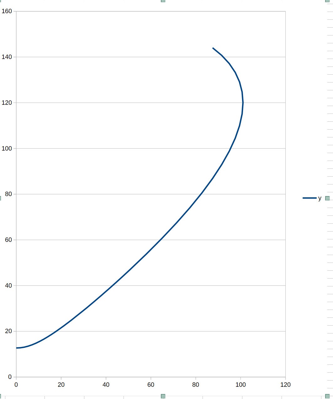
Been following this thread for a while and your work has been amazing. One of the things that has stuck in my head for a while is wondering if there was a more continuous way to handle the round over than the SE. I threw a quick formula into excel using an ellipse rather than a skew line to define the OS profile and ended up with a result pretty close to one of your K=1 curves (attached alone and overlayed on your K=1 curve from a pdf on your website)
The basic thought was that for a pure OS, you have a a line rotated off parallel from the axis by some skew angle that gets swept around said axis. That line could also defined as a segment of a circle with infinite radius. If we make the radius of that circle finite, you start to get profiles that naturally terminate. My first attempt at a skewed circular sweep profile led to some extremely wide round overs, so I tried using an ellipse instead.
The formula from the spread sheet was Y =SQRT((Rthroat+(Rmouth-Rmouth*COS(aE))/eE)^2+(xE*TAN(aE))^2)
Where:
Rthroat = Throat radius (12.7mm)
Rmouth = Mouth radius (130mm)
aE = angle along defining ellipse (from 0-120 deg in this example)
eE = elongation of ellipse (1.73 in this example)
xE = axial distance at aE = =Rmouth*SIN(aE))*COS(aS)
aS = Skew angle or waveguide angle (39 deg)
I wish I could also supply some AKABAK results, but sadly I keep getting zero size errors and can't seem to get things running. I was interested in this family of profiles because it seems like plug molds could be produced with an ellipse cutting jig offset above a lazy susan
Attachments
Hi Trevor,I was interested in this family of profiles because it seems like plug molds could be produced with an ellipse cutting jig offset above a lazy susan
- "an ellipse cutting jig"? How would that look like? 🤔
I need some time to process your formula, but I understand your idea of revolving an ellipse instead of a straight line (definitely an original one!). But your very idea led me immediately to another one - it didn't occur to me until now but the profile can be as easily expressed as a function x( y ), i.e. inverted. Then to get a rolled-back profile, we would just subtract SE from the raw OS in the x direction. Funny, perhaps no parametric description is required after all, this seems as even more elegant (it's a PITA working with R-OSSE sometimes, as some things must be done numerically).
BTW, the current implementations are already pretty smooth - I think it will be tough to make them even more so.
Last edited:
Hi TrevorF,
The reason for asking is that I actually used a similar idea. I mounted a Styrofoam comprising doughnuts of increasing diameters glued together on a rotary table, and used straight hot wire angled and tangential to several points along the axis. Rotating the table resulted in piece-wise rough cut. I then attached a template to a rod through the center of the rotary table and using car body filler spread over the piece-wise rough cut to obtain a final shape. .
It is rather laborious process, namely re-positioning and accurately angling the hot wire, hence my interest in your idea.
Kindest regards,
M
Like Marcel, I was wondering if you could please explain, how would you implement the jig?I was interested in this family of profiles because it seems like plug molds could be produced with an ellipse cutting jig offset above a lazy susan
The reason for asking is that I actually used a similar idea. I mounted a Styrofoam comprising doughnuts of increasing diameters glued together on a rotary table, and used straight hot wire angled and tangential to several points along the axis. Rotating the table resulted in piece-wise rough cut. I then attached a template to a rod through the center of the rotary table and using car body filler spread over the piece-wise rough cut to obtain a final shape. .
It is rather laborious process, namely re-positioning and accurately angling the hot wire, hence my interest in your idea.
Kindest regards,
M
It's a bit like a circle cutting jig for a router but you have a second pivot pin. The two pins set the major and minor radius. Each pin rides in a rail, and the two rails are perpendicular to each other. There's a few article/youtube vids out there for how to make them and I think Rockler sells pre-made ones
- Home
- Loudspeakers
- Multi-Way
- Acoustic Horn Design – The Easy Way (Ath4)