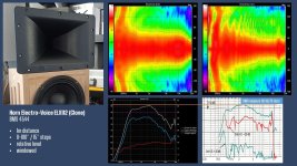
Hi mabat, a really awesome match with your simulation. Nice.- It seems that the center of rotation was ~18 cm from the throat 🙂
View attachment 1200224
Regarding the ripples between 500-3k, I guess this has not much to do with the waveguide. Could be a reflection off a nearby object.
You're right, the rotation center was 18,5cm and yes I have measured your simulated vertical response.
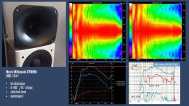
The absolute fall off in HF with the BMS 4544 is something I measured across all my tested CD like horns. I have also the BMS 4550 driver but it is quasi identical frequency wise. Here are BMS own measurements with the 4544 on a CD Horn: BMS Measurement
In the attached files I scaled the BMS measurement to my own accordingly. It behaves up to 7-8 kHz similar to my measurements. But in the range of 7-20kHz it is different. I will cross check with a second uncalibrated measurement mic I have on hand.
Attachments

Thanks, it's good to know that there isn't anything too suspicious going on.The absolute fall off in HF with the BMS 4544 is something I measured across all my tested CD like horns. I have also the BMS 4550 driver but it is quasi identical frequency wise.
I just have to share this - I've come across a loudspeaker that uses a compression driver phase plug, turned inside out as an "ultra high sound" tweeter. I never saw anything like this before. What an idea is that? 🙂


They probably listened to a CD without horn I thought it was great. A few threads here about hornless compression driver adventures...
//
//
The ATHEX 460-25 with the TD-2001 throat section modeled:


- It has only a very little effect on the radiation pattern (i.e. it won't start beaming) but of course there are impedance issues. We already saw, however, that it doesn't have to be so strong effect in the end. Honestly I still don't know what exactly to expect.
- It has only a very little effect on the radiation pattern (i.e. it won't start beaming) but of course there are impedance issues. We already saw, however, that it doesn't have to be so strong effect in the end. Honestly I still don't know what exactly to expect.
Last edited:
The same for the ATHEX-E-280-25:


One wouldn't expect a huge difference between these two horns caused by the impedance alone...
One wouldn't expect a huge difference between these two horns caused by the impedance alone...
Last edited:
What's the physical interpretation of a negative imaginary part of the throat impedance?
There are cases when it's never negative:

In the above examples it's not the case. What does it mean?
There are cases when it's never negative:
In the above examples it's not the case. What does it mean?
Hi Marcel,
Re post #13,438, your understanding is correct.
Re more specific example, this is the best I could think of. Referring to your whitepaper OS-SE Waveguide.pdf, the generalized OS is described by Eg. (3) , the termination by Eq. (4), and the terminated generalized OS by Eq. (5).
As best as I understand given the design parameters, from the Length and Rollback.Start.At the program calculates the length of the generalized OS as (Length* Rollback.Start.At) and using Eq. (3) calculates the generalized OS profile. The program then calculates the length of the termination as (1- Length* Rollback.Start.At).
I do not know, how it continues from there. Given the Length, the starting coordinates of the termination, and the Rollback.Angle, there appear to be infinite number of super-ellipses that can be generated. Thus, additional limitations are required, most naturally equality of a 1st derivative about the common point of the generalized OS (tanget) and the termination, which is still insufficient so in addition equality or close fit of a 2nd derivative about the common point of the generalized OS (curvature).
With this understanding, a naïve approach would be to replace Eg. (3) with an equation of the polynomial:
r_pol(z) = a*z^3 + b*z^2 + c*z + d (3’)
with the parameters [a, b, c, d] known.
This does not appear to be reasonable, given the need to re-write the program, and your lack of motivation to continue the development.
However, this may not be necessary, if it would be possible to make the program to accept the starting coordinates of the termination and the 1st and the 2nd derivative, so that the termination can be correctly calculated. In that regard,
If even that is not possible, I have been thinking about the following approach. Since the starting coordinates of the termination [r_pol(z_end); z_end] are known, use Eq. (3) to determine the remaining parameters: r0, alpha, alpha0, and k to obtain least square approximation of the polynomial of Eq. (3’).
The problem is that I do not know if this can be solved analytically, and even if so, if I am able to do so. Thus, the fallback is to write a program that would step through “reasonable” ranges of the r0, alpha, alpha0, and k, and select the closest fit.
Please let me know if I am on the right track, or completely off. Of course, should some of it were considered a "secret sauce" that you do not wish to disclose, please do not reply to such.
Kindest regards,
M
I haven't thought this through, but you could write the impedance as r x exp(i x phi). Normally r would be the gain and phi the phase (shift).What's the physical interpretation of a negative imaginary part of the throat impedance?
I guess it will be something along these lines (acoustic compliance?): https://www.diyaudio.com/community/...-design-the-easy-way-ath4.338806/post-6868185
@mefistofelez - I'll return to you after I get familiar with it enough 🙂
@mefistofelez - I'll return to you after I get familiar with it enough 🙂
Does it help if you can supply coordinates?Hi Marcel,
Re post #13,438, your understanding is correct.
Re more specific example, this is the best I could think of. Referring to your whitepaper OS-SE Waveguide.pdf, the generalized OS is described by Eg. (3) , the termination by Eq. (4), and the terminated generalized OS by Eq. (5).
As best as I understand given the design parameters, from the Length and Rollback.Start.At the program calculates the length of the generalized OS as (Length* Rollback.Start.At) and using Eq. (3) calculates the generalized OS profile. The program then calculates the length of the termination as (1- Length* Rollback.Start.At).
I do not know, how it continues from there. Given the Length, the starting coordinates of the termination, and the Rollback.Angle, there appear to be infinite number of super-ellipses that can be generated. Thus, additional limitations are required, most naturally equality of a 1st derivative about the common point of the generalized OS (tanget) and the termination, which is still insufficient so in addition equality or close fit of a 2nd derivative about the common point of the generalized OS (curvature).
With this understanding, a naïve approach would be to replace Eg. (3) with an equation of the polynomial:
r_pol(z) = a*z^3 + b*z^2 + c*z + d (3’)
with the parameters [a, b, c, d] known.
This does not appear to be reasonable, given the need to re-write the program, and your lack of motivation to continue the development.
However, this may not be necessary, if it would be possible to make the program to accept the starting coordinates of the termination and the 1st and the 2nd derivative, so that the termination can be correctly calculated. In that regard,
If even that is not possible, I have been thinking about the following approach. Since the starting coordinates of the termination [r_pol(z_end); z_end] are known, use Eq. (3) to determine the remaining parameters: r0, alpha, alpha0, and k to obtain least square approximation of the polynomial of Eq. (3’).
The problem is that I do not know if this can be solved analytically, and even if so, if I am able to do so. Thus, the fallback is to write a program that would step through “reasonable” ranges of the r0, alpha, alpha0, and k, and select the closest fit.
Please let me know if I am on the right track, or completely off. Of course, should some of it were considered a "secret sauce" that you do not wish to disclose, please do not reply to such.
Kindest regards,
M
https://www.diyaudio.com/community/...-design-the-easy-way-ath4.338806/post-7228138
It is an acoustic compliance. Seeing as how little effect the radiation impedance has on the mechanical system, it's not a big deal. Positive imaginary is mass and negative is compliance (this, of course, depends on ones choice of sign convention in the calculations as it is arbitrary, although one has to remain consistent. Physicists tend to use the opposite convention from EE. Can cause no end of confusion.)I guess it will be something along these lines (acoustic compliance?):
Hi Marcel,
Hi Tom,
Thank you for your reply.
What my problem reduced to its essence is; having a curve, characterized by an end-point [r_end; y_end] and 1st and 2nd derivative at this point, in terms of ATH the end-point of the generalized OS, and an additional limitation, e.g., overall length and overall end-point and 1st and 2nd derivative at this point, in terms of the terminated generalized OS the end-point of the termination section, and calculate the termination section between these points.
This is akin to a problem in laying train-tacks or roads. There is a first portion of the train-tack or the road and second portion of the train-tack or the road, generally in two different locations and angles with respect to each other. The problem to be solved is to generate a curve connecting these two portions with matching 1st and 2nd derivation at the end-point of the first section and the end-point of the second section.
There is (usually) an additional limitation of minimal acceleration through the connecting curve, thus using Euler spiral. Marcel has investigated this, but since the Euler spiral has no analytical solution, he decided to use a super-ellipse with known analytical solution.
What I am questioning is, whether Marcel's program, that was written with matching specific curves, generalized OS and supper-ellipse, can be somehow convinced to match a polynomial with super-ellipse.
Kindest regards,
M
Thank you, but, please do not waste too much time on that, as noted in my reply to Tom, I am trying to use your tool for something it was not designed to do.@mefistofelez - I'll return to you after I get familiar with it enough 🙂
Hi Tom,
Thank you for your reply.
Please correct me if I am wrong, but what you have been attempting to inquire about was, whether you can replace the wave-guide (entire) profile calculation with an arbitrary profile defined by a set of vectors [r; y], correct?Does it help if you can supply coordinates?
What my problem reduced to its essence is; having a curve, characterized by an end-point [r_end; y_end] and 1st and 2nd derivative at this point, in terms of ATH the end-point of the generalized OS, and an additional limitation, e.g., overall length and overall end-point and 1st and 2nd derivative at this point, in terms of the terminated generalized OS the end-point of the termination section, and calculate the termination section between these points.
This is akin to a problem in laying train-tacks or roads. There is a first portion of the train-tack or the road and second portion of the train-tack or the road, generally in two different locations and angles with respect to each other. The problem to be solved is to generate a curve connecting these two portions with matching 1st and 2nd derivation at the end-point of the first section and the end-point of the second section.
There is (usually) an additional limitation of minimal acceleration through the connecting curve, thus using Euler spiral. Marcel has investigated this, but since the Euler spiral has no analytical solution, he decided to use a super-ellipse with known analytical solution.
What I am questioning is, whether Marcel's program, that was written with matching specific curves, generalized OS and supper-ellipse, can be somehow convinced to match a polynomial with super-ellipse.
Kindest regards,
M
OK, maybe I now understand better what you mean, but within the OS-SE formula there's in fact no such matching of curves, no separate curves to be connected. A superelliptical (SE) arc is merely added to a (generalized) OS curve, both as simple functions y(x) over the same interval. It's a superposition, one plus the other, not a connection. This sum then resembles an Euler spiral as a result (that's how it was motivated) but that's all.
In a general case you could take just any curve, like an OS curve alone, and by an algorithm modify the coordinates of its points so that the curvature is smoothly increased (starting at some point, and at a defined rate along the curve length) - that's exactly how the original Rollback algorithm worked. I abandoned it when I came up with the R-OSSE formula that made it just a lot more elegant.
- I have no clue how to optimally (in any sense) connect two curves... That's not what are the formulas doing.
So is it possible to say that a negative imaginary means that there's an amount of air surrounding the source, that is just compressed and rarefacted but it doesn't lead to a wave radiation? It's difficult to imagine, maybe even more than an acoustic mass...It is an acoustic compliance.
Hi Marcel,
thank you for the answer.
r(z) = r_pol(z) + r_term(z)
wherein:
r_pol(z) = a*z^3 + b*z^2 + c*z + d,
r_term ( z) = (s * L / q) * [1 −(1−( q * z / L) ^n )^1/n]
and it will work? That would solve my problem.
I have to think about it because I do not comprehend how it can guarantee that the 1st and 2nd derivative at the "common" point agree between the superimposed curves. But, then again, I am not a math whizz, like yourself.
In any event, thank you for your time.
Kindest regards,
M
thank you for the answer.
A superelliptical (SE) arc is merely added to a (generalized) OS curve, both as simple functions y(x) over the same interval. It's a superposition, one plus the other, not a connection.
Are you saying that one can replace the generalized OS: r_gos(z) Eq.(3) in Eq. (5) with the polynomial and leave the super-ellipse: r_term(z) Eq. (4):In a general case you could take just any curve, like an OS curve alone, and by an algorithm modify the coordinates of its points so that the curvature is smoothly increased (starting at some point, and at a defined rate along the curve length)
r(z) = r_pol(z) + r_term(z)
wherein:
r_pol(z) = a*z^3 + b*z^2 + c*z + d,
r_term ( z) = (s * L / q) * [1 −(1−( q * z / L) ^n )^1/n]
and it will work? That would solve my problem.
I have to think about it because I do not comprehend how it can guarantee that the 1st and 2nd derivative at the "common" point agree between the superimposed curves. But, then again, I am not a math whizz, like yourself.
In any event, thank you for your time.
Kindest regards,
M
But there's no "common point" to match - those two curves don't need to match anywhere. When you add two smooth functions (with no jumps in derivatives, like any polynomial), their sum will be no less smooth - that's guaranteed, you don't have to worry about that.I have to think about it because I do not comprehend how it can guarantee that the 1st and 2nd derivative at the "common" point agree between the superimposed curves.
By adding a SE part to whatever "base" function, you just change its shape - the SE part simply "bends" the base function smoothly. Coincidentally, it works for OS+SE so that it forms a termination resembling a clothoid (and it's in fact much smoother than a truncated OS+connected clothoid would ever be), but what it will look like for a general polynomial depends on the polynomial...
Last edited:
It's difficult for me to imagine it as well. I just know that is what it is. I don't have a feel for how it comes about. It could be a sloshing of the media in front of the diaphragm.So is it possible to say that a negative imaginary means that there's an amount of air surrounding the source, that is just compressed and rarefacted but it doesn't lead to a wave radiation? It's difficult to imagine, maybe even more than an acoustic mass...
Even stranger, when I worked on sonar heads of 100's of transducers, you had to calculate the impedances of each transducer with all the other ones at their expected values hardly ever in phase with each other. In rare case the REAL part could go negative and the transducer would blow up.
- Home
- Loudspeakers
- Multi-Way
- Acoustic Horn Design – The Easy Way (Ath4)