Your post is gold, thank you @PlanarGianca . The 4 boards I have didn't come with any USB sticks. I do have one from another board though. Perhaps I can make it work? The pinouts are definitely not the same.
Not sure what you got, but the USBi that worked for me is this one:
https://www.ebay.com/itm/1143262509...uid=OHWSZXdgQgW&widget_ver=artemis&media=COPY
also from aliexpress:
https://www.aliexpress.us/item/3256...!sea!US!133567712!&curPageLogUid=LOwMIWuS05br
https://www.ebay.com/itm/1143262509...uid=OHWSZXdgQgW&widget_ver=artemis&media=COPY
also from aliexpress:
https://www.aliexpress.us/item/3256...!sea!US!133567712!&curPageLogUid=LOwMIWuS05br

It looks like the same that I have just without the ribbon. I just have to match the pins 🙂
Member
Joined 2018
Yes, It neededIt looks like the same that I have just without the ribbon. I just have to match the pins 🙂
It's like this way...
.
The USBi connection with the ADA1452-AD1938 (aka CS42448) are pretty straightforward.
The documentation I found online matches the labels on both the board and the USBi, however, while both connections seemed to work fine without errors, only the SPI connection ended with a successful in-out config for me.
I didn’t investigate further, cuz ain’t gonna fix what’s not broken, so YMMV.


The documentation I found online matches the labels on both the board and the USBi, however, while both connections seemed to work fine without errors, only the SPI connection ended with a successful in-out config for me.
I didn’t investigate further, cuz ain’t gonna fix what’s not broken, so YMMV.
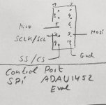
- Definition of the link mode between USBi and target board (ADAU1452dsp board):
SPI communication mode: 1/3/5/7/9 (CLK/CS/MISO/MOSI/GND) of the USBi terminal of the simulator corresponds to 5/4/3/2/1 of the CN2 of the target board (ADAU1452 dsp board), which is just in order.
I2C communication mode: 2/4/6 (GND/SCL/SDA) of the USBi terminal of the simulator corresponds to 1/5/3 of the CN2 of the target board (ADAU1452 dsp board).
Member
Joined 2018
Thanks, PlanarGianca-San,
Lucky to know this... 👍
CyberPit
This means a genuine ADI USBi user should change its pinout connections anyway.The USBi connection with the ADA1452-AD1938 (aka CS42448) are pretty straightforward.
The documentation I found online matches the labels on both the board and the USBi, however, while both connections seemed to work fine without errors, only the SPI connection ended with a successful in-out config for me.
Lucky to know this... 👍
CyberPit
Hm I can't seem to edit the post. I found I had CLK connected to SCLK instead, fixed that but that did not seem to make a difference.
SPI1 to 1-2, power on unit - unit has green/blue steady light. Link/compile/download in Sigmastudio. Not sure what "everything checks out from HW config page" means? The USBi stays green if that matters.
Erase mem, write mem via DSP seems do to something in Sigmastudio but the board does not appear to be affected. (SPI mode 0 or 3 when writing does not seem to make a difference)
Power off the unit, set SIP1 jumper to 2-3, power on unit. Now the unit powers on like when it was new, that is it has a red/purple flashing LED. Pushing MPI7 button seems to switch between programs or modes:
1) (default power on) - blinking red/purple
2) blinking blue/purple
3) blinking green/purple
4) steady purple light < this one passes audio through (but still no Sigmastudio control)
I2C address 0x76 (118) seems to be correct, it does change the LED behavior when the board is booted up in SPI1 2-3 setting...
Ok, you succeeded in erasing the board to its default settings: when it is in red/purple blinking mode, that is where it is at.Hm I can't seem to edit the post. I found I had CLK connected to SCLK instead, fixed that but that did not seem to make a difference.
SPI1 to 1-2, power on unit - unit has green/blue steady light. Link/compile/download in Sigmastudio. Not sure what "everything checks out from HW config page" means? The USBi stays green if that matters.
Erase mem, write mem via DSP seems do to something in Sigmastudio but the board does not appear to be affected. (SPI mode 0 or 3 when writing does not seem to make a difference)
Power off the unit, set SIP1 jumper to 2-3, power on unit. Now the unit powers on like when it was new, that is it has a red/purple flashing LED. Pushing MPI7 button seems to switch between programs or modes:
1) (default power on) - blinking red/purple
2) blinking blue/purple
3) blinking green/purple
4) steady purple light < this one passes audio through (but still no Sigmastudio control)
When the led it's steady blue/green, it means it is with the SP1 in the 1-2 position and ready to be programmed.
Now you need to download your program on it: it seems you are missing step #5 in my procedure.
I attached my test IN-OUT sigma project for you to test: use it at your own risk...
Remember that I only connected inputs 1 and 3: for input 2, you are on your own.
Break a leg...
Attachments
So is the workflow like this?
1. SPI1 in 1-2 position
2. F7 to compile, then step 5 (download via DSP)
3. Turn off board, change SPI1 to 2-3 position
4. Turn on board, press MPI3 button a couple of times to change to 4th program which has steady LED and allows audio throughput
5. If any programming / change is to be done (no realtime Sigmastudio communication is possible with this board such as read registers or change mute on the fly) - turn off board, SPI1 to 2-3 position, power on, go to step 1
Only your steps above from 1 to 3 are necessary: once you download your project into the chip once rebooted should be a bright steady kinda-blue light, and you do no need to press any of the buttons since you are not longer using the smt2 chip functions.So is the workflow like this?
1. SPI1 in 1-2 position
2. F7 to compile, then step 5 (download via DSP)
3. Turn off board, change SPI1 to 2-3 position
4. Turn on board, press MPI3 button a couple of times to change to 4th program which has steady LED and allows audio throughput
5. If any programming / change is to be done (no realtime Sigmastudio communication is possible with this board such as read registers or change mute on the fly) - turn off board, SPI1 to 2-3 position, power on, go to step 1
I tried your project file 1452_cs42448192i2s_Test_v3.dspproj and also 1452_cs42448192i2s.dspproj
Then I made follwing steps :
1. SPI1 in 1-2 position
2. F7 to compile, then step 5 (download via DSP)
3. Turn off board, change SPI1 to 2-3 position
but still no Sigmastudio control
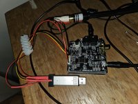
I connected the delivered USBi Stick to a standard ADAU1452Eval ( see drawing ) and I had successful control with SigmaStudio
Then I made follwing steps :
1. SPI1 in 1-2 position
2. F7 to compile, then step 5 (download via DSP)
3. Turn off board, change SPI1 to 2-3 position
but still no Sigmastudio control
I connected the delivered USBi Stick to a standard ADAU1452Eval ( see drawing ) and I had successful control with SigmaStudio
Attachments

Last edited:
I wonder if the FreeUSBi and the non-free one (for some $50 or so per this thread) is the issue? I can't imagine it would be though, as the protocols (I2C / SPI) are well defined, but IDK......
Not sure why I can't seem to get any readback from the board at all. Perhaps we need a Youtube video from the user on here that has it working, showing from start to finish, step by step, what is needed to get some kind of Sigmastudio interaction with this board.
Not sure why I can't seem to get any readback from the board at all. Perhaps we need a Youtube video from the user on here that has it working, showing from start to finish, step by step, what is needed to get some kind of Sigmastudio interaction with this board.
I dunno. I shared everything I got.
Cant even test it right now: I think I bricked the codec board by using an over zealous power supply.
Waiting for a replacement, should be here next week.
Cant even test it right now: I think I bricked the codec board by using an over zealous power supply.
Waiting for a replacement, should be here next week.
I might make a couple of more attempts using I2C, instead of SPI, as I did get some reactions from the board then.
Isn't it crazy how one (say, a company) would release a totally unusable board and charge money for it? Talk about a shady market.
Isn't it crazy how one (say, a company) would release a totally unusable board and charge money for it? Talk about a shady market.
I got the replacement board yesterday, and I still get consistent results when I followed my procedure and download my simple 4in-8out program.Isn't it crazy how one (say, a company) would release a totally unusable board and charge money for it? Talk about a shady market.
Well, we get what we pay for… if you want a more reliable 1452+1938 board with extensive documentation and support, you can always get the official learning one:
https://www.analog.com/en/design-ce...ards-kits/EVAL-ADAU1452RevBZ.html#eb-overview
I’ll definitely get that one for one of my next projects.
- Home
- Source & Line
- Digital Line Level
- low cost ADAU1452 China board...