Hmm... hmm... hmm...... however: beta = Ic / Ib
Lots of pondering.
That statement is not untrue... it is what it is really.
I had to wrap everything around outside and inside my head again.
What is the right place to determine the beta?
It is embedded in the U3D opamp output, but not neccessary the best spot to extract the beta data.
So, your suggestion (#61) to measure the actual Ib is 'the best place to be'.

So let's develop the circuit from this point onwards (as Mark prefers to obstruct verifications with tina of the progressions above sofar with riddles for unknown reasons), and have your suggestion folded into the mathematical analysis - I've made a block diagram of it.
And as you can notice, the current source involved is centered around R55 ('R5' in the calculations), and is the ultimate candidate to measure Ib at the same time!
Only another (fine, reliable, easy to tweak, thanks TI!) INA, and the subtraction of that 'Vgen-carrier' yields to a sound beta trace, as far as I can foresee for now.
I hope to see some results from your build soon - I keep looking over your shoulder for further support.
Attachments
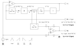
The base resistor.What is the right place to determine the beta?
Again my schematic, which obviously should work.
Instead of INA103, I will use AD620 or pincompatible INA111, the FET opamp buffers then are not needed.
V3 will be a sawtooth, later possibly followed by a log amp (selectable).
Unfortunately I could not find a logamp in my collection of ICs, so need to buy that one.
The falling edge of the sawtooth will be used to trigger a timing circuit to sample Ic and Ib, so a LED display for both hfe and Ic can be added.
A cursor signal can be injected into the X output.
Vce selection is still omitted in the schematic.
I posted my desired roadmap earlier here:
If we use a asymmetric sawtooth generator, we can use the falling edge to trigger a monostable multivibrator with variable pulse width.
Something like CD4538.
From there a sample/hold freezes/updates the beta voltage for direct digital readout of hfe.
At the sampling point another very short pulse could be triggered, and a analog switch would add in a resistor parallel to the feedback resistor of the Y amp, so a small square bump cursor appears on the curve. Maybe you have another idea for a cursor.*
And while we`re at it, we could readout the current at the cursor position too. ☕
*We could couple a short hf burst into the Y signal, that would appear as a square dot 🙂
More possible additions for later:
Switchable linear - logarithmic scale.
Adjustable lower current limit.
More possible additions for later:
Switchable linear - logarithmic scale.
Adjustable lower current limit.
Last edited:
There is a curve tracer design on the site
https://www.paulvdiyblogs.net/2021/03/building-curve-tracer-version-3.html
Some time ago there was lots of detail on what went on in Tektronix units but seems it was hard to duplicate so picked another design. The intro linked to mentions problems with using digital scopes for a display.
For small signal there are lots of info and videos on this rather simple tracer
https://www.eddybergman.com/2017/06/simple-but-effective-transistor-curve.html
The rather simple square wave generator shown can produce very fast edges.
Some years ago when I bought one of this brand of usb scopes I was tempted to get one of their curve tracers. The scope is very good. Excellent prices too. A problem with this sort of thing is the need to maintain the software as well. Looks like the main driving force behind the company has died. Enquires aren't answered.
https://www.syscompdesign.com/product/ctr-201/
It uses a programming language that may be called TCL or similar with TK added. Probably an ideal choice but java may be more stable.
https://www.tcl.tk/about/uses.html
Not fully following the wish for log sweeps etc but a PC can display values in linear or log given the data needed
Your links are about curve-tracers (Ic = f (Vce) ), not about a 'beta-tracer' (ß = f (Ic) ), which is addressed in this topic.
The title of the thread is curve tracers. Beta can be calculated from the output and is HFE anyway both of which will vary according to VCE.which is addressed in this topic.
Transistor HFE - IC curve tracer?The title of the thread is curve tracers.
Curves are magnetic, not to polarise though.
Keep me informed (pm if preferred), lots of issues unaddressed still. Had some further thoughts also.
(((circumferencing mark's prohibition)))
(((circumferencing mark's prohibition)))
Answer as a friend... erwwhh... nope.
What scope is that (recognising a past?)?
What's the middle bnc, what X. what Y?
What scope is that (recognising a past?)?
What's the middle bnc, what X. what Y?
Middle BNC is sawtooth input, however not good signal. Need onboard generator.
There are issues with stability which I have partially fixed already.
Transistors with different beta result in equal span, so the feedback loop works.
This is a small Iwatsu scope with small tube.
There are issues with stability which I have partially fixed already.
Transistors with different beta result in equal span, so the feedback loop works.
This is a small Iwatsu scope with small tube.
new footage 🙂
MAT02, Yout on a digital scope. IMHO XY will not be needed.
Note the measured Level 6,39V which translates to a beta of 639.
The chinese hfe tester shows 653.
3 different transistors show a consistant deviation which is obviously coming from the white 0,1ohm 10% resistor.
Next step is to reduce INA gain from 500 to 50, there seems to be noize.
Last edited:
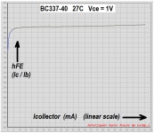
Traces still not clean but beta droop of a BC548 can be seen with 40mA Ic span.
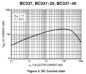
ONsemi datasheet:
...note the log Ic scale...


ONsemi datasheet:
...note the log Ic scale...
Last edited:
Some transistors make problems with the circuit.
BD139 breaks up into oscillations above 20mA.
Now this one is bad: MPS6515 40mA span

BD139 breaks up into oscillations above 20mA.
Now this one is bad: MPS6515 40mA span
update
I reduced the INA gain from 500 to 50 and increased sense resistors x10. Noise is nearly gone. That means, keep INA gain as low as possible.
Also added a pF cap and no more oscillations.
With high Ic span still ghost trace artefacts from hf overcompensation somewhere.
Again, MPS6515 40mA span, compare with last post.
- Home
- Design & Build
- Equipment & Tools
- Transistor HFE - IC curve tracer?