What is the gate/source voltage of each FET with the current set as low as it will go? although I suspect the issue is more oscillation related as much as anything else.
Those voltages are quite high and will turn on the lateral FET's quite hard.
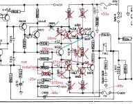
So all those parts circled are removed? Try lifting R642 which should make the gate/source voltages close to zero. See what happens when you do that.
So all those parts circled are removed? Try lifting R642 which should make the gate/source voltages close to zero. See what happens when you do that.
gate is zero with that removedThose voltages are quite high and will turn on the lateral FET's quite hard.
So all those parts circled are removed? Try lifting R642 which should make the gate/source voltages close to zero. See what happens when you do that.
no it still has noise on the right, not as much, a tiny bit if you turn it up on the left
but thats at practicaly no bias
If you increase the good(left channel to 7mv(what it would be with BJT'S fitted) the lamp is REALY bright
the bad channel you cannot get below 30+mv and thats plugged into the lamp, with a mains voltage of 220ac
i dare not try that at the moment without the lamp
but thats at practicaly no bias
If you increase the good(left channel to 7mv(what it would be with BJT'S fitted) the lamp is REALY bright
the bad channel you cannot get below 30+mv and thats plugged into the lamp, with a mains voltage of 220ac
i dare not try that at the moment without the lamp
And is that with R642 still lifted? In other words do you still have zero gate voltage and yet still have 30mv across the 0.22 ohm?the bad channel you cannot get below 30+mv and thats plugged into the lamp, with a mains voltage of 220ac
If so then a probably reason for the good channel lighting the bulb is simply that it pushes the bulb current over the edge where the bulb suddenly increases its filament resistance and lights.
If it is all as described above then look with the scope on the gates of each FET but do this on the bias generator end of the gate resistor rather than on the gates. Is the noise/oscillation still present?
This is with that resistor fitted. Without it is 0v.
the 0.22 resistors have been removed and have jumpers. If I plug in full mains I can't even get the good channel below 30mv
the 0.22 resistors have been removed and have jumpers. If I plug in full mains I can't even get the good channel below 30mv
It is getting very confusing to follow is this 🙂
How are you measuring the bias current if the original emitter resistors are linked out?
When you say this:
Where is the 30 mv? I took 'source' to mean the source pin of the FET and so between speaker output source would be across where the 0.22 ohm is.
Going right back to the beginning of the thread I think the other channel is still all OK. Is that correct?
How are you measuring the bias current if the original emitter resistors are linked out?
When you say this:
i cannot get the voltage down to less than 30mv with the presets(MM across speaker terminal and scource), no matter what
it will increase if you go high enough but that drags the main supply down.
Where is the 30 mv? I took 'source' to mean the source pin of the FET and so between speaker output source would be across where the 0.22 ohm is.
Going right back to the beginning of the thread I think the other channel is still all OK. Is that correct?
I think you need to confirm first of all the good channel really is OK (and that means disabling the other one if it runs to hot) and powering it up on full mains once you are happy. Make sure the good channel adjusts, is oscillation free and sounds OK.
I removed these early on as per your instruction. Do you want me to put the 0.22's back?Are you comparing like for like?
What was the resistor value you were measuring across to get 7mv for the BJT and is it the same value resistor you are using for the FET's.
The BJT 3140 uses 0.22 ohm emitter resistors as I recall but for the FET's we don't those and they are better linked out
Its perhaps not a bad idea while we try and see what is going on.
(how are you determining the bias current without those fitted, remind me... I know I ask a lot of questions and some might be repetitive but its hard keeping it all together sometimes along with everything else on here 🙂)
(how are you determining the bias current without those fitted, remind me... I know I ask a lot of questions and some might be repetitive but its hard keeping it all together sometimes along with everything else on here 🙂)
All I am doing at the moment is measuring the voltage as you would have done if the BJT'S were fitted. So with a multi meter between the speaker terminal and FET source
That's what I don't get.
If you have the 0.22 ohm linked out then the speaker output to FET source is a piece of wire... no? yes? 🙂
the 0.22 resistors have been removed and have jumpers.
If you have the 0.22 ohm linked out then the speaker output to FET source is a piece of wire... no? yes? 🙂
So how do you get 30mv across a piece of wire. Do you see 🙂 ?
You should not see any voltage at all under any condition if they are linked or are you thinking of DC offset rather than the voltage across the 0.22 ohm?the 0.22 resistors have been removed and have jumpers. If I plug in full mains I can't even get the good channel below 30mv
no not the offset
vr603/4 are and have always been connected directly to the drain or what would have been the emmiter on the BJT
the only difference is that the 0.22ohm has been removed
This is the original test point location, it was just located on top of the resistor
this is how i am taking the readings, and did the same on all the others without issue
Attachments

- Home
- Amplifiers
- Solid State
- NAD 3140 Conversion to lateral FETS