That doesn't sound good. If both channels failed the same way (no sound) then I wonder if something catastrophic like a rail problem occured (that would effect both channels) then it could cause a DC offset......
First just check the amp with no speakers attached. Check the rails and DC offset. Then check your speakers on a different amp. If a major issues had happened then I would have thought the rail fuses would have blown.
It might be a good idea in future for you to have speaker protection board so that any amp problem with an amp you are working on will not damage speakers. AC coupling is probably the easiest by making a large bi-polar cap from two suitable electrolytics.
so then, the culprit, sometimes you get lucky and find things quickly
now the noise gets 10x worse if you connect a lead from the cd player, no music,just plugged in so it has to be a ground issue doesnt it?
now the noise gets 10x worse if you connect a lead from the cd player, no music,just plugged in so it has to be a ground issue doesnt it?
Attachments
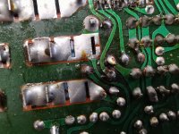
Cracked print around the pad? It also looks like the solder hasn't taken to the component lead. Hitachi were bad for that kind of thing.
The noise/lead issue does sound a bit like a floating or missing ground.
The noise/lead issue does sound a bit like a floating or missing ground.
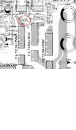

The manual shows a 50 volt rail and a 2k2 feeding the LED and the parts list shows a 1/4 watt part, the update says increase to 4k7 at 1/2 watt. That is potentially still over 1/2 watt dissipation while the original worked out at over 1 watt in a 1/4 part.
This kind of thing was NAD's downfall imo, so much stuff is marginal in its safety margins.
This kind of thing was NAD's downfall imo, so much stuff is marginal in its safety margins.

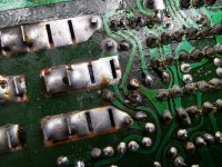
That looks pretty substantial. Haven't seen resistors like that in years although I do have a Belco signal generator that is full of them in all wattage sizes.
Belco Generator
Belco Generator
It is very easy to overload an amp with many generators. To much signal and to high a frequency (at a high level) and many amps will object. Look and learn the output levels from the generator and always use the correct attenuator settings. That little Belco puts out 8 volts pk/pk from memory but from a high and variable source impedance (amplitude pot wiper) while my Tenma function generator does 20 volts pk/pk from 50 ohms at anywhere from sub 1 Hz to a couple of Mhz.
I have a bucket full if one day you need it, an old technician gave it to me about thirty years ago.That looks pretty substantial. Haven't seen resistors like that in years although I do have a Belco signal generator that is full of them in all wattage sizes.
Belco Generator
it tends to oxidize and split at the incerts which are fitted on either side of the resistance.
so here is where i am.
i have no noise unless i take the current above 30ma, and TBH it sounds fine set at this
but could i trust it not to go wrong,only time and testing i guess will prove that, but in the mean time im still not convinced, so i shall keep on looking
i have no noise unless i take the current above 30ma, and TBH it sounds fine set at this
but could i trust it not to go wrong,only time and testing i guess will prove that, but in the mean time im still not convinced, so i shall keep on looking
There is no real reason it should go wrong as a circuit configuration although that obviously excludes anything lurking like intermittent bad connections/print etc. As far as freedom from the output stage being damaged or failing I would say the lateral FET's should be many orders more reliable than the bjt configuration. The FET's do not suffer thermal runaway.
I've never worked on the NAD's in practice and so the reality of them is an unknown in terms of layout and how well thought out the grounding really is. When you turn the bias current up you automatically increase the ripple on the unregulated rails. That is a possible route for hum/noise injection and comes down to how the various nodes of the circuit interact and connect to ground. Each channel is bound to be different in that regard due to board layout configuration.
If its silent at 30ma then perhaps leave it at that although you could say its always good to find out why something happens even if it comes down to layout and board design.
The ripple component on the unregulated rails will always be present but it is the value of the current draw from a rail that determines how much ripple (its amplitude on the rail) there is.
Amps have a figure in the specs called PSRR or power supply rejection ratio and it is a measure of how they reject or ignore ripple on the rails. Layout of circuit boards and particularly grounding make a massive difference.
Amps have a figure in the specs called PSRR or power supply rejection ratio and it is a measure of how they reject or ignore ripple on the rails. Layout of circuit boards and particularly grounding make a massive difference.
- Home
- Amplifiers
- Solid State
- NAD 3140 Conversion to lateral FETS