Hmmm...
This is the 3020 we did originally but the concept is the same. Without the 0.22 ohms fitted there is no way to measure a voltage and so derive a quiescent current value.
Your 3140 Test file above shows TP2 being as what looks like the emitter of one of the power transistors. That makes sense, the instructions are saying you measure across one of the 0.22 ohms and adjust for 6mv. 6mv across 0.22 ohm is 27 milliamps. It all sounds reasonable.
So you show this.

And I can find this in a full manual:

This shows a measurement between Gate (one of the end pins) and the output line which doesn't tell us the bias current.

The only way to measure the bias current is either directly by breaking the circuit (messy) or by calculation across a known resistor such as a 0.22 ohm. Ideally once its all done we do not want the 0.22 ohms fitted but as a means of checking current they work well.
Whatever is going on with the measurements, the preset should be able to bring the current to zero and the bulb should be out. If we need more range on the multiplier we can fix that. If you lift that R642 resistor (we did the other day) on both channels you should have zero bias current and the should essentially work normally.
Does that make sense 🙂
This is the 3020 we did originally but the concept is the same. Without the 0.22 ohms fitted there is no way to measure a voltage and so derive a quiescent current value.
Your 3140 Test file above shows TP2 being as what looks like the emitter of one of the power transistors. That makes sense, the instructions are saying you measure across one of the 0.22 ohms and adjust for 6mv. 6mv across 0.22 ohm is 27 milliamps. It all sounds reasonable.
So you show this.
And I can find this in a full manual:
This shows a measurement between Gate (one of the end pins) and the output line which doesn't tell us the bias current.
The only way to measure the bias current is either directly by breaking the circuit (messy) or by calculation across a known resistor such as a 0.22 ohm. Ideally once its all done we do not want the 0.22 ohms fitted but as a means of checking current they work well.
Whatever is going on with the measurements, the preset should be able to bring the current to zero and the bulb should be out. If we need more range on the multiplier we can fix that. If you lift that R642 resistor (we did the other day) on both channels you should have zero bias current and the should essentially work normally.
Does that make sense 🙂
Missed that image off. We know this works.This is the 3020 we did originally but the concept is the same. Without the 0.22 ohms fitted there is no way to measure a voltage and so derive a quiescent current value.
......... vr603/4 are and have always been connected directly to the drain or what would have been the emitter on the BJT.
the only difference is that the 0.22ohm has been removed.............
I believe that VR603 need to go to the GATE (base for bipolar) of Q626, not directly wired to the .22 ohm resistor.
I took your red wire in your "Current Situation" (SIC) to simply be inaccurately drawn, The blue wire is good.
As commented already, the 0.22 ohm is not essential when using certain types of MOSFET, but it is needed for easy measuring of quiescent current (essential if you want to use the original instructions from the manual for bias adjustment).
The
Yes that makes senseHmmm...
This is the 3020 we did originally but the concept is the same. Without the 0.22 ohms fitted there is no way to measure a voltage and so derive a quiescent current value.
Your 3140 Test file above shows TP2 being as what looks like the emitter of one of the power transistors. That makes sense, the instructions are saying you measure across one of the 0.22 ohms and adjust for 6mv. 6mv across 0.22 ohm is 27 milliamps. It all sounds reasonable.
So you show this.
View attachment 1195041
And I can find this in a full manual:
View attachment 1195042
This shows a measurement between Gate (one of the end pins) and the output line which doesn't tell us the bias current.
View attachment 1195043
The only way to measure the bias current is either directly by breaking the circuit (messy) or by calculation across a known resistor such as a 0.22 ohm. Ideally once its all done we do not want the 0.22 ohms fitted but as a means of checking current they work well.
Whatever is going on with the measurements, the preset should be able to bring the current to zero and the bulb should be out. If we need more range on the multiplier we can fix that. If you lift that R642 resistor (we did the other day) on both channels you should have zero bias current and the should essentially work normally.
Does that make sense 🙂
You are right I have drawn it wrong on there. It does go to the gateI believe that VR603 need to go to the GATE (base for bipolar) of Q626, not directly wired to the .22 ohm resistor.
I took your red wire in your "Current Situation" (SIC) to simply be inaccurately drawn, The blue wire is good.
As commented already, the 0.22 ohm is not essential when using certain types of MOSFET, but it is needed for easy measuring of quiescent current (essential if you want to use the original instructions from the manual for bias adjustment).
The
View attachment 1195050
so fitted the 0.22's back in and its adjustable now and stable at 7mv per channel (0.3636ma) but i still have noise on the right channelHmmm...
This is the 3020 we did originally but the concept is the same. Without the 0.22 ohms fitted there is no way to measure a voltage and so derive a quiescent current value.
Your 3140 Test file above shows TP2 being as what looks like the emitter of one of the power transistors. That makes sense, the instructions are saying you measure across one of the 0.22 ohms and adjust for 6mv. 6mv across 0.22 ohm is 27 milliamps. It all sounds reasonable.
So you show this.
View attachment 1195041
And I can find this in a full manual:
View attachment 1195042
This shows a measurement between Gate (one of the end pins) and the output line which doesn't tell us the bias current.
View attachment 1195043
The only way to measure the bias current is either directly by breaking the circuit (messy) or by calculation across a known resistor such as a 0.22 ohm. Ideally once its all done we do not want the 0.22 ohms fitted but as a means of checking current they work well.
Whatever is going on with the measurements, the preset should be able to bring the current to zero and the bulb should be out. If we need more range on the multiplier we can fix that. If you lift that R642 resistor (we did the other day) on both channels you should have zero bias current and the should essentially work normally.
Does that make sense 🙂
OK, so 7mv across 0.22 ohms gives us 7e3-3/0.22 which is 32 milliamps. That's fine for now. The bulb should not be lit brightly at that bias level. Leave the bias as it is and leave the resistors in place for now.
I would suggest retracing and reconfirming what is happening now. Connect the scope to the speaker output and look at the noise.
If the noise is a buzz or hum it is low frequency and that is what you are hearing. If there is a also a high frequency component present then that is another separate issue. So look at the noise and determine the peak to peak amplitude (which gives us an idea of how loud it is) and also look at the low frequency fundamental and calculate the frequency. It is most likely to be 50 or 100Hz which gives a repetition rate of 20 or 10 milliseconds respectively.
If there is a high frequency component as well then what is the repetition rate of that. For example 300kHz would be 3.3uS (microseconds) per cycle. You can't hear that but if anything like that is present then it can cause weird effects lower down the frequency range.
Good advice from Mooly there.
Leave the bias as is until you have solved all other issues with the amp, after which you should increase it as far as the heat-sink will allow. Hopefully you should be able to double, ideally tipple the bias.
Molly also hints at oscillations. This made me realize that the PCB layout is not made with MOSFET in mind and you have not put gate resistors.
The connections you have between bias transistor Q632 and the MOSFET gates should be replaced by resistors.
Resistors are typically used in this location to avoid oscillations.
Personally I would start with 1K resistors until all issues are solved, then after all other issues are solved, look at reducing them (typical final values would be 220-330 ohm for the N-FET and 330-470 ohm for the P-FET).
These resistors should be mounted close to the MOSFET. There are also long traces going from the FET gate to R656, C620, Q616 etc as noted in purple and tan in the image below. The trace should be cut close to the MOSFET gate (or resistor mentioned above placed between Gate and PCB)
EDIT: I see in post 81 and Moolys reply in post 82 that you already have 270 ohm gate resistors. Not easy to give good advice when presented schematic is inaccurate. Anyway, as Mooly points out in post 82 - the long wire from the gate-stopper resistor looks a bit long. Given the length of this wire, I would increase from 270 ohm to 820 or 1000 ohm while troubleshooting as mentioned above. Also as Mooly points out in post 82, if you don't solder the resistor on the PCB you wont have to cut the traces as I recommended above.
Last edited:

so i knew it wasnt wire lengths or resistor values as it was ok on the other channel
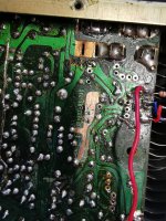
its all working good now, there was, and it took somefinding, a dodgy bit of track, that is now repaired with a new pice of jumper wire, that i presume was a factory mod, you cant even see it in the photo, but that track had no continuity.this proves grounding from the other side of the board
Is got crackly switches and a little bit of noise still that ill track down,but it is barely audible
but basicaly it is on full mains and works ok
I will look, as suggested into increasing the bias once im happy it isnt going to go haywire again
Ive currently got it on test and it sounds ok so far
The board needs a good clean up now and some of the soldering too as it must have been worked on before
also the switches are crackly and need a good clean
Attachments
Well that's good to hear and well done for finding the problem 👍 Things like can be difficult to trace sometimes.
(Have we had enough of NAD's now 😉)
(Have we had enough of NAD's now 😉)
Maybe after fixing the 25 I have in my work area. I was thinking of doing a conversion of a marantz unit
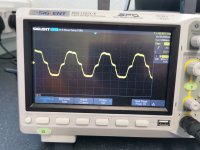
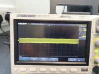
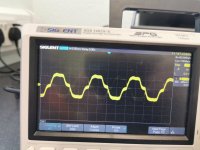
so here is whats left to find.
quite odd realy
pictures left to right
1-speaker switch in 'A' possition
2-speaker switch in 'off' possition
3-speaker switch in 'B' possition
4-speaker switch in 'A/B' possition
quite odd realy
pictures left to right
1-speaker switch in 'A' possition
2-speaker switch in 'off' possition
3-speaker switch in 'B' possition
4-speaker switch in 'A/B' possition
Attachments

Everything you are seeing on the scope needs quantifying. You say it sounds OK and that the noise has gone having earlier found that break in the print.
Sometimes oddities are down to measurement set ups and connection points and grounding and (depending on the level of what you see) may just be all that can be expected from such a circuit. The NAD never claimed to be a highly specced design but it was a design that sounded really really good.
For example if you connect your scope across the speaker wires at the amp end of the wires (but don't have the wires actually connected to the amp) you might well see something like you show in that last picture. That is the leads and wiring picking up stray noise and hash that is 'everywhere' with all our modern switching supplies and mobiles and wifi.
I did say in that post there was still a faint noise to track down. The scope is connected across the speaker terminals and the noise is quite a low fequency buzz and not loud, not affected by the volume control at all and no external inputs connected
These can be very difficult things to track down. Always remember that the amplifier circuit itself does not buzz or hum but rather the noise comes either from injection via a rail or it appears as a 'signal' between to sensitive nodes in the circuit such as ripple current generating a volt drop along a ground conductor and then having two nodes of the amp connected to different points on that ground connection.
I think I would first try isolating everything at the input of the, perhaps lifting the left end of this coupling cap and connecting that lifted end to the appropriate ground (circled) and see if the noise is reduced.
I know its not easy, you have to be ruthlessly methodical and try and determine where the noise is getting into the chain.
That is an unexpected twist. Obvious first check has to be that the power supply is up and running.
Everything seems normal, but I did start hearing really loud clicks and bangs when I was turning other items on and off, like the CD player. Now all I'm getting is what I can describe as a very faint transistor radio type sound out of one speaker. I just hope they haven't been damaged by some spike or other
- Home
- Amplifiers
- Solid State
- NAD 3140 Conversion to lateral FETS