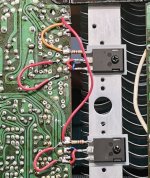
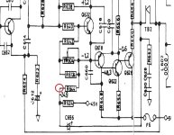
Hmmm. I think I would take those two red loops out and make a short link in their place. You could even just add a single link from the centre pin to wherever it goes on the board. That very long lead to the gate of the lower FET looks a bit scary as well.
The gate of the lower FET. There is no need to connect the gate to the unused print. That just adds stray 'all sorts' into the mix 😀 So that left hand end of the 270 ohm gate stopper, I would lift connection off the unused print.
Also have you tried moving or touching those wires to see if the noise alters or goes?

It could be on a knife edge and the other channel may not be that far behind.
I would definitely try adding a small cap across the feed back resistor as mentioned.
Shorten and neaten those wires. Make them direct links and if there is nothing on the PCB they need to go to then miss connecting them to the board altogether. Just link the points concerned directly. I know they just look like short bits of wire (and you're thinking what harm can that do) but at HF they appear and behave as anything but a short piece of wire. There is significant impedance there. Decoupling the Drains close to the FET's (the rails) to ground via a small cap could help as well.
I wish I could give you a simple answer but its not that straightforward 🙂
That's a good attitude 👍
You'll gain lots of insight and experience with things like this.
You'll gain lots of insight and experience with things like this.
so here is something strange, maybe you guys can enliten me
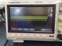
This is what it looks like at the speaker terminals(all 8) with all 6 fuses removed
so it is noise, but not audible with the fuses out inc the mains fuse
This is what it looks like at the speaker terminals(all 8) with all 6 fuses removed
so it is noise, but not audible with the fuses out inc the mains fuse
Attachments
Last edited:
right so i have learned somethinghere today.
this noise is as a result of the long ground lead i had on the probe
if i remove it and use the standard length there is no noise
so where so i go from here as i cant check things across the board with the standard ground that comes clipped to the probe.
this noise is as a result of the long ground lead i had on the probe
if i remove it and use the standard length there is no noise
so where so i go from here as i cant check things across the board with the standard ground that comes clipped to the probe.
This is what it looks like at the speaker terminals(all 8) with all 6 fuses removed
so it is noise, but not audible with the fuses out inc the mains fuse
If there is no load on the output then you will likely see all sorts of stray pickup. Its all just floating. Even adding something a like 1k or 100 ohm as a load should remove that.
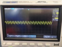
That does look more like ripple because it has the characteristic sawtooth shape of typical ripple. If you look at the frequency it should be 100Hz and not 50Hz. That means there should be10ms between any two similar points on the waveform.so this is what it realy looks like
ripple right?
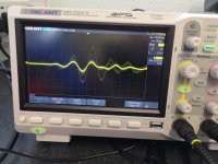
That does look like instability made up of different components.
You need to look at the frequency of the low frequency repetition. There are two cycles of that per division so look at the timebase speed and calculate the frequency. I'm guessing it will be 100Hz. Then increase the timebase speed and expand the other parts which will be high frequency.
You need to look at the frequency of the low frequency repetition. There are two cycles of that per division so look at the timebase speed and calculate the frequency. I'm guessing it will be 100Hz. Then increase the timebase speed and expand the other parts which will be high frequency.

this noise is as a result of the long ground lead i had on the probe
if i remove it and use the standard length there is no noise
so where so i go from here as i cant check things across the board with the standard ground that comes clipped to the probe.
https://www.analog.com/en/technical-articles/short-ground-leads-make-better-scope-photos.html
Jim Williams (RIP) wrote this great application note "high speed amplifier techniques", discussing proper probing/ Well worth sitting back and reading:
https://www.analog.com/media/en/technical-documentation/application-notes/an47fa.pdf
https://www.analog.com/media/en/technical-documentation/application-notes/an47fa.pdf
ok some odd voltages going on here around the pre set, so im going to have a look here for a bit
Its good you are keeping looking at it. These kind of things are where you learn an awful lot once it all starts to come together.
I have only been able to spend a few hours at a time on this and it has migrated.
I dont think noise is the issue(although it is an issue, but this is being caused by the very high currents
The faulty channel cannot be adjusted down any further than +38mv(speaker terminal to source) so i need to find this current draw first
I dont think noise is the issue(although it is an issue, but this is being caused by the very high currents
The faulty channel cannot be adjusted down any further than +38mv(speaker terminal to source) so i need to find this current draw first
Do you mean the bias current? 38mv is going to be around 170ma with those 0.22 ohm resistors. The voltage across the bias generator needs to be able to get down to pretty low levels to give low bias current in FET's. Compare with the other channel.
so i took those resistors out along time ago(as instructed), so i have no real reference
i cannot get the voltage down to less than 30mv with the presets(MM across speaker terminal and scource), no matter what
it will increase if you go high enough but that drags the main supply down.
I need it to be about 7-9mv realy to acheive what it would have been originaly
i cannot get the voltage down to less than 30mv with the presets(MM across speaker terminal and scource), no matter what
it will increase if you go high enough but that drags the main supply down.
I need it to be about 7-9mv realy to acheive what it would have been originaly
- Home
- Amplifiers
- Solid State
- NAD 3140 Conversion to lateral FETS