If the lamp brightens at 1.22ma bias current then something else unseen is going on I think. That level of current would barely light an LED let alone cause a filament lamp to glow.
Everything (to me) seems to point to HF instability somewhere. All these things looked at from a DC point of view don't make sense. I think you will have to get creative by disabling one channel and concentrating on the other. Your scope should be good enough to pick up anything going on.
Everything (to me) seems to point to HF instability somewhere. All these things looked at from a DC point of view don't make sense. I think you will have to get creative by disabling one channel and concentrating on the other. Your scope should be good enough to pick up anything going on.
ive just been looking at this again, and im sure my calculations are right, which must mean it isnt 1.22ma, but 1.2AIf the lamp brightens at 1.22ma bias current then something else unseen is going on I think. That level of current would barely light an LED let alone cause a filament lamp to glow.
Everything (to me) seems to point to HF instability somewhere. All these things looked at from a DC point of view don't make sense. I think you will have to get creative by disabling one channel and concentrating on the other. Your scope should be good enough to pick up anything going on.
0.27mv/0.22 would be 1.2A not ma
the origianl spec with BJT's only called for 0.06/0.22 =27ma, so no wonder the lamp was glowing with 1.2a (that is right isnt it?)
If you 0.27 mv then the current in 0.22 ohm is just 1.2ma which certainly would not light the bulb. That is why I think there is something else going on.
There are quick ways to estimate all these. I=V/R so 0.22 volts across 0.22 ohm would be 1 amp, 0.022 volts (22mv) would be 0.1 amp and 2.2mv would be 0.01 amp and so on.
There are quick ways to estimate all these. I=V/R so 0.22 volts across 0.22 ohm would be 1 amp, 0.022 volts (22mv) would be 0.1 amp and 2.2mv would be 0.01 amp and so on.
6mv across the 0.22 ohm is 27mathat means the original bias current with BJT's would have been 1.22ma 6mv/0.22
i can see whats wrong here, ithought i was doing it wrong, but i wasnt, i was using the reading i set it at (27mv)
so 27mv/0.22, but i had the decimal point in the wrong place 0.27/0.22 instead of 0.027/0.22
so the reading would have been 0.122ma, so the lamp would be bright at that right?
so 27mv/0.22, but i had the decimal point in the wrong place 0.27/0.22 instead of 0.027/0.22
so the reading would have been 0.122ma, so the lamp would be bright at that right?
Last edited:
so given the original spec was for 27ma, is that sufficieint? it does work at those levels
the good channel is more than capable of going up to 50ma
the good channel is more than capable of going up to 50ma
It is enough to reduce the crossover distortion to very low levels but there also has to be a reason why it is doing this. If you have one channel that does not light the bulb at a given setting and yet the other channel does then something is obviously different and the only thing I can think of is that it is some form of AC (HF instability) issue.
so here is where we are at, and i think it might narrow it down a bit
The noise is unaffected using the volume control, increase in bias is the only thing that affects 'the volume of the buzz'
using the balance control does not influence it in any way, that is if you turn that channel off with the balance control, the noise remains unchanged
removing the pre/main amp links has no affect, so its power amp side, not pre
so this is where i will concentrate my efforts today
so im kind of confused now as the attached sine is the same on the good, as well as the bad channel
current progress isnt alot realy other than the noise goes away if i disconnect the gate stopper from the 'P'channel transistor
If i do the same with the 'N' channel the noise if still there
current progress isnt alot realy other than the noise goes away if i disconnect the gate stopper from the 'P'channel transistor
If i do the same with the 'N' channel the noise if still there
Attachments
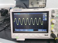
The scope trace looks a bit 'furry' unless its just the image. I wouldn't advise disconnecting the gate stoppers because the FET's have a near infinite input resistance and the gate will just pick up and float to any random voltage.
Any noise you are hearing in the speaker will be very very low amplitude indeed, perhaps only a few millivolts peak to peak and you would only see that with no signal.
Why is sine clipped at the top and bottom? Is the input waveform clipped like that?
Any noise you are hearing in the speaker will be very very low amplitude indeed, perhaps only a few millivolts peak to peak and you would only see that with no signal.
Why is sine clipped at the top and bottom? Is the input waveform clipped like that?
- Home
- Amplifiers
- Solid State
- NAD 3140 Conversion to lateral FETS