I think I still have a problem. I spend some time checking resistor values but not found anything wrong until now even that it can be difficult to see if a ring is red or brown. Then with some "in-circuit" measurement I could conclude the color.
I can adjust the rails to -+15 VDC with no problems but the M1/M2 gets too hot.
After 5 min or so I measured with heat-gun M1/M2 to 106 C which is too hot?
Is there a M1/M2 gate voltage I can check to see if it is wrong?
I can put heatsink on until I have found the error.........
Now......the M3 circuit I have not implemented because I do not implement the relays.
Is that the error......that it will reduce the load of M1/M2?
use DMM
compare what parts you put in pcb with schematic
I can give you voltages, but that will not help much
I mean - there will always be 0V65 as Vbe for T1/T2, but entire world of difference in programmed current if there is no proper resistance and thus parts heating (Q1, Q2, M1, M2)
main thing is - what resistance is put for reg CCS (Q1, Q2) programming current?
I mean, what's problem comparing parts with schematic?
When you say "no proper resistance" do you mean that the PSU needs a load?
For R3/R4 and R5/R6 I used all 15R and I measured that the total R = 7R5. Those are the CCS resistors?
Then I have not populated: R25, M3, ZD1, ZD2, C11 and no relays are implemented.
My assumption was that the above components all have to do with relay choke power.
Apart from that all components should be as schematic. I use 10k2 instead of 10K and R26/R27 are 200k instead of 220k (the Rin).
I have found some heatsinks for M1/M2.
dunno what's the case with your build
same all, I can keep my fingers all the time on M1/M2, without heatsinks
relay PSU is all before shunt regs, as is proper
anyway, if you did everything by the book, install heatsinks on M1, M2, then chill
btw. you have approx. 0V65/7R5=87mA for programmed current
error amp taking few mA
buffers taking, say, 15mA
means leftover 60mA for M1 and M2
with 15V rail, that's 900mW of heat per M
use htsnk or not, your choice
heat-IR guns - most of them are simply stupid; only expensive ones certainly good
What I believe he is trying to tell you in his ZM-pediodactic fashion (meaning that what to do is up to you to figure it out), is to measure the voltage drop across R23 and R24. And triple check the value of those two resistors too.
With a good DMM, you may be able to measure the R also, 330R. May be unstable, but I have succeeded many times in circuit with a Fluke.
With a good DMM, you may be able to measure the R also, 330R. May be unstable, but I have succeeded many times in circuit with a Fluke.
Andy, which schematic you're looking at?
R23/24 are M1, M2 gate resistors; no voltage there (edit: across those)
if you're thinking of R3 & R4 (R5 & R6) - there is always 0V65 across, no matter what their resistance is

R23/24 are M1, M2 gate resistors; no voltage there (edit: across those)
if you're thinking of R3 & R4 (R5 & R6) - there is always 0V65 across, no matter what their resistance is
Last edited:
I did check R23 / R24 and those are 330R. I can measure voltage drop. I should expect almost no current I assume.
I will also check voltage across R3/R4 to check if voltage is 0.65V. The T1/T2 could be damaged caused by the swap of Q1/Q2.
I can measure with temp probe also.
When M1/M2 gets heatsinks I can measure more "relaxed". I have some that are 33mm tall that fits. I assume those will make a difference.
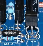
Have a look at U1 in picture (the voltage 2V5 reference). The legs had to be bended a bit to have it fit into the PCB. I assume I did correct?
I could make a very quick check of T1/T2 0.65V......if voltage is higher......then I know the problem and T1/T2 needs to be exchanged.
I will also check voltage across R3/R4 to check if voltage is 0.65V. The T1/T2 could be damaged caused by the swap of Q1/Q2.
I can measure with temp probe also.
When M1/M2 gets heatsinks I can measure more "relaxed". I have some that are 33mm tall that fits. I assume those will make a difference.
Have a look at U1 in picture (the voltage 2V5 reference). The legs had to be bended a bit to have it fit into the PCB. I assume I did correct?
I could make a very quick check of T1/T2 0.65V......if voltage is higher......then I know the problem and T1/T2 needs to be exchanged.
Attachments
I measure 1.5V over R3/R4 and 0.66V over R5/R6 so I guess T1 is bad (I checked that it is a BC546A and correct mounted)?
I had fingers on both M1/M2 and M1 gets much warmer that M2. I had all my attention on M1 so I think M2 is ok regarding temperature.
I had fingers on both M1/M2 and M1 gets much warmer that M2. I had all my attention on M1 so I think M2 is ok regarding temperature.
Correct schem but incorrect brainAndy, which schematic you're looking at?
R23/24 are M1, M2 gate resistors; no voltage there (edit: across those)
if you're thinking of R3 & R4 (R5 & R6) - there is always 0V65 across, no matter what their resistance is
 (or typing faster than the brain works, whatever suits me)
So I take it one two of the things he actually needs to verify is the actual value of his R3,4,5 and 6, and function and pinouts of his BJT’s.
Gate resistors is for weaklingzezzez anyways
I measure 1.5V over R3/R4 and 0.66V over R5/R6 so I guess T1 is bad (I checked that it is a BC546A and correct mounted)?
I had fingers on both M1/M2 and M1 gets much warmer that M2. I had all my attention on M1 so I think M2 is ok regarding temperature.
go, just repair it
much easier to replace even all semis inside than needlessly writing on forum
I mean, it is so simple ......
I did cover (pretty much) function on every part in Iron Pre, in KISS and this thread
besides - positive and neg circs are mostly just mirror like - if one is good, you have all what's needed to look as recipe for repairing other one
put small heatsinks on M1/M2/M3 if that make you happy/er
My M1, M2 get a bit warmer than Q1, Q2, so I'm using the same 19x20 U-shaped heatsinks there. They don't go above 40 C now. Maybe because the AC voltage of the toroids measures 19V, not 18V?
Btw, I'm not using M3.
As an aside, this concept continues to bake my noodle. A voltage without a current*? Or the converse, for AC after it's passed through a capacitor or inductor, a current without voltage? (at an instant in time, per a phase plot of current and voltage)R23/24 are M1, M2 gate resistors; no voltage there (edit: across those)
*Yes yes I know putting a 10 megohm voltmeter across two points will draw an infinitessimal current in order to sense the potential difference. But I don't believe that potential difference only came into existence by virtue of applying a 10 megohm resistance, hence my claim of a potential without a current. This is all very Zen, I have no answers.
^ Here's where I get into trouble... big trouble... The good news is that I'm not averse to public humiliation.
Note - below is an attempt for me to learn... As witnessed in many other situations... I'm wrong A LOT... stop here if you're not interested in what might be nonsense.
You can have a potential difference, but no current flow. In this case... the way the (let's say M1) transistor "opens" is when the potential difference between the gate and the source is greater than the Vgs_th (and in the correct polarity).
The little electron buddies are all piled up higher on one side than the other... That's the potential difference. However, they don't get to go through the gate... that would be gate leakage. No current between gate and drain or gate to source ... the current flows from drain to source (or vice versa).
Yet another bold and public attempt to see if I actually grasp even a piece of how this stuff works.
Last edited:

if you can properly measure any significant (in fact - measureable) voltage sag across 330R gate resistors of M1 and M2, you're most likely done some major ookoop in preamp assembly, meaning you didn't had great peace of mind, when needed
in fact, IPre is so simple that you need to make at least 2 at once, to have any significant time of great piece of mind
now, if that's not the case, and your preamp is working as intended, find appropriate basic electronic book , where mosfets are compared with toobz, saying that they're governed with voltage (meaning - minuscule current demands of governing pin) ...... process that for 3mins, then use your time for some music indulgement
Something would have likely broken down the gate... oopsie. I think...if you can properly measure any significant (in fact - measureable) voltage sag across 330R gate resistors of M1 and M2, you're most likely done some major ookoop in preamp assembly, meaning you didn't had great peace of mind, when needed
Hello @ACnotDC, I am interested as well. Sent you a pm.The idea, schm and BOM was posted at #336 and #344 in this thread. More data, Gerber and so on via PM, if interested
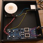
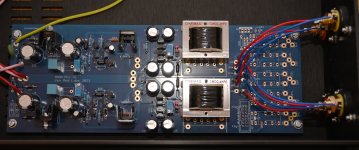
I can't braid. This a woman's work, not mine and this way I have a Kimber cable in PSU...

After replace of the BC546A for the positive rail-CCS the amp seems to "behave".
I put small clip-on heatsinks on the M1/M2. Without they raised to about 60C and with heatsinks I estimate temp to be approx. 50C.
They still gets a bit warmer than the BD's. I use 7R5 as CCS "resistor" so about 85 mA CCS current. It depends on Rds_on for M1/M2 how hot they gets?
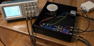
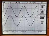
After adjusting rails and offsets I tried the amp using a small battery powered 1000 Hz generator. The scope shows both outputs. It is X1 but scope thinks it is X10 so Voltages shown should be divided by 10. Jumpers set to 6 dB.
Generator set at max. output I measure 5.2V RMS at output which I think is correct when set to 6 dB.
It looks like a sinus even that the old Tek has a rather coarse display?
I don't know if I should make some noise/distortion measurements or try to listen how it sounds.
I use DAC as preamp.......if some wonder why there is no pot.......
There are no mechanical hum from the transformer.......100% silent......which is nice.
I put small clip-on heatsinks on the M1/M2. Without they raised to about 60C and with heatsinks I estimate temp to be approx. 50C.
They still gets a bit warmer than the BD's. I use 7R5 as CCS "resistor" so about 85 mA CCS current. It depends on Rds_on for M1/M2 how hot they gets?
After adjusting rails and offsets I tried the amp using a small battery powered 1000 Hz generator. The scope shows both outputs. It is X1 but scope thinks it is X10 so Voltages shown should be divided by 10. Jumpers set to 6 dB.
Generator set at max. output I measure 5.2V RMS at output which I think is correct when set to 6 dB.
It looks like a sinus even that the old Tek has a rather coarse display?
I don't know if I should make some noise/distortion measurements or try to listen how it sounds.
I use DAC as preamp.......if some wonder why there is no pot.......
There are no mechanical hum from the transformer.......100% silent......which is nice.
Attachments
- Home
- Amplifiers
- Pass Labs
- Iron Pre Essentials Kits For The DIYA Store - Register Your Interest