Yes, simple.
What is simple also is the calibration procedure of the Iron (not to close jumper before DC-offset is zero etc.).
I read it somewhere but yesterday I could not find it. I just want to read it again to be sure I don't miss a tiny detail.
About the primary fuse for the Toroidy 20 VA type toroid (230 VAC) I got this answer from Toroidy:
"Use T160mA or T180mA fuse".

The idea, schm and BOM was posted at #336 and #344 in this thread. More data, Gerber and so on via PM, if interested...please share more details on the Arduino based volume control and display pcbs ...

I can't braid. This a woman's work, not mine and this way I have a Kimber cable in PSU...Braids are nice but at least in theory not the technique...

It's on the schematics.What is simple also is the calibration procedure of the Iron (not to close jumper before DC-offset is zero etc.).
I read it somewhere but yesterday I could not find it. I just want to read it again to be sure I don't miss a tiny detail.

Yes, only 6 dB but XLR balanced output are usually x2 of RCA (SE) output. Then the absolute output voltage of the BAL version is the same as the SE set at 12 dB. This would be my case with the DAC I have which has both XLR and RCA outputs.I think the balanced version only at 6dB?
Russellc
PMed you regarding the volume controlThe idea, schm and BOM was posted at #336 and #344 in this thread. More data, Gerber and so on via PM, if interested
I can't braid. This a woman's work, not mine and this way I have a Kimber cable in PSU...
Thanks
I did the first power up of SE Iron-pre using a vario-transformer.
At about 180 VAC in I measured about 13-14 VDC at the U- and about 5-6 VDC at U+.
But when I put my finger on the M2 transistor it was very hot. I would estimate 60-70 C.
Then I turned down the voltage immediately.
How hot are those M1/M2 expected to be?
I suspect something to be wrong?
Are there any test-points I can measure to ensure DC levels around are correct?
PM sentPMed you regarding the volume control
Thanks
I did the first power up of SE Iron-pre using a vario-transformer.
At about 180 VAC in I measured about 13-14 VDC at the U- and about 5-6 VDC at U+.
But when I put my finger on the M2 transistor it was very hot. I would estimate 60-70 C.
Then I turned down the voltage immediately.
How hot are those M1/M2 expected to be?
I suspect something to be wrong?
Are there any test-points I can measure to ensure DC levels around are correct?
as said - check everything
if nada, then pics
you made some error with parts value or position
Another thing, make sure you've used the correct toroidal leads together. There was a mistake with mine (locally made), but I picked it up by measuring the AC voltage of the pairs of leads. The manufacturer swapped around the colors of two wires. You need two pairs of leads that measure near identical voltage. Mine showed around 19VAC.
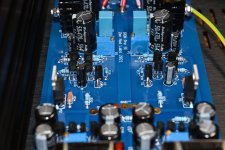
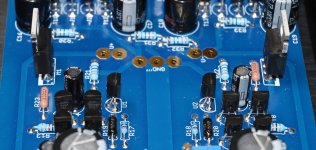
I will attached some pictures in a moment. If the + on silkscreen is correct I think caps are mounted correct (I checked a lot of times). The white stripes on caps are minus (-). I did not test the transistors before I mounted them. I will prepare some pictures.........
Regarding the resistors they are mounted symmetric meaning that if there is an error the error is on both sides.
Regarding the resistors they are mounted symmetric meaning that if there is an error the error is on both sides.
That's why I'm wondering if you paired the correct toroidal leads. Please measure the AC voltages with the power leads not connected to the board.Regarding the resistors they are mounted symmetric meaning that if there is an error the error is on both sides.
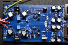
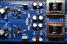
Some images attached. Great if someone can find an error. The two channels behaved very different. +rail raised much slower than -rail.
AC secondary seems ok and also the diodes as I could measure correct DC after diodes.
I will have a detailed look also.......if you need further details (e.g. colors on resistors.....just ask 🙂 ).
AC secondary seems ok and also the diodes as I could measure correct DC after diodes.
I will have a detailed look also.......if you need further details (e.g. colors on resistors.....just ask 🙂 ).
Attachments

it's so easy - in positive rail all bjts are NPN, and one P channel mos
in negative rail all bjts are PNP and one N channel mos
I mean, there is sooooooo many parts to check, hardly worth collective forum efforts
I Mean - work something ..... and give some info
check AC voltage
check DC right after bridges
and yes - each cap is having carefully marked + beside, I was thinking how to make your life easier
- Home
- Amplifiers
- Pass Labs
- Iron Pre Essentials Kits For The DIYA Store - Register Your Interest