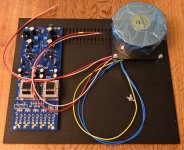
Regarding how secondary is connected I used one of the pairs (red/pink) as they are shown at image. The yellow flex is the phase indicator. Red/red is 18 VAC and pink/pink also 18 VAC. Then I connected the two secondary's as in serie like two batteries (1 to +). It also seemed that when I measured at the two anodes and the two cathodes on diodes it looked like correct DC.That's why I'm wondering if you paired the correct toroidal leads. Please measure the AC voltages with the power leads not connected to the board.
Attachments

I was very keen about the small transistors.......but maybe I did something wrong with the MOS.......will check those first......it's so easy - in positive rail all bjts are NPN, and one P channel mos
in negative rail all bjts are PNP and one N channel mos
I mean, there is sooooooo many parts to check, hardly worth collective forum efforts
I Mean - work something ..... and give some info
check AC voltage
check DC right after bridges
and yes - each cap is having carefully marked + beside, I was thinking how to make your life easier
I think that is the error........before I have even checked.......
MOS was correct but BD140 in the positive rail........
Hope the hot MOS in the negative rail survived + JFETs etc........
Hope the hot MOS in the negative rail survived + JFETs etc........
Ha!
I just stumbled on terrific smart idea!!
At least half of Greedy Boyz can obtain substantial financial infusion with extracleveronlyZMcanthinkofit trick - just sell all of your measuring instruments
I mean - who needs them .......... money got for these is best to invest in buying fancy resistors and fancy wire and fancy solder and fancy transistors and fancy caps and fancy connectors and fancy what not
measurements - heck - who need that, we don't even need schematic

I'm fairly certain, somewhere... I posted a very strong recommendation to purchase and use one of the Mega testers (or similar) when sorting parts.
I stand by that recommendation.
Everyone makes mistakes, but those little gizmos have saved me a great deal of time and effort. For this build as an example, I could not separate 556s from 546s without one.
Not selling my gadgets. We have "Prime Day" here through Amazon. My cart was full of cheap and cheerful gizmos. I still don't have my differential probe for my scope yet... but... a fella can dream. Now, I just do it the cheater's way and use two channels.
I did sold all my measuring thingies
differential probe gone with scope

differential probe gone with scope
a fella can dream
gizmos are nice but IME it is always important to think twice before probing 
ZM - Your measurement instruments at the ends of your arms and on either side of your noggin are so finely tuned that no electronic tools could ever come close anyway. You probably solder blindfolded just for a challenge.

Not going there... not near there... anywhere...gizmos are nice but IME it is always important to think twice before probing
In my old life I had to weld closed eyed to match crap vintage welding on chrome-moly chassis. Used ears to hear the flame.Solder blindfolded
Yeah just send all yr unwanted oscilloscopes and distortion analyzers to OGBDF, left coast branch. We're always open.Ha!
I just stumbled on terrific smart idea!!
At least half of Greedy Boyz can obtain substantial financial infusion with extracleveronlyZMcanthinkofit trick - just sell all of your measuring instruments
I mean - who needs them .......... money got for these is best to invest in buying fancy resistors and fancy wire and fancy solder and fancy transistors and fancy caps and fancy connectors and fancy what not
measurements - heck - who need that, we don't even need schematic
can't
everything sold, including piles of paper schematic and all my pc screens
don't need stinkin' schmts
even this typing without screen, sorta blindfolded, checkin' on my fuzzy Crystal Ball
everything sold, including piles of paper schematic and all my pc screens
don't need stinkin' schmts
even this typing without screen, sorta blindfolded, checkin' on my fuzzy Crystal Ball
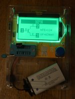
I have this device among others.........one of the unsoldered devices still works.
I ended up cutting the legs so I need new ones.......a task for the weekend.
The measurement devices do not ensure that you don't swap components.......by a mistake.
The vario-transformer may have saved me as I never passed 180 VAC.......and I avoided smoke.....
I ended up cutting the legs so I need new ones.......a task for the weekend.
The measurement devices do not ensure that you don't swap components.......by a mistake.
The vario-transformer may have saved me as I never passed 180 VAC.......and I avoided smoke.....
Attachments
Great news that all may be okay. If you need replacements for anything, let me know.
Oh the smoke I've created...
It's all fun stuff. Hope it's an easy-peasy part swap with no further drama.
Or... reading them incorrectly...The measurement devices do not ensure that you don't swap components.......by a mistake.
Oh the smoke I've created...
It's all fun stuff. Hope it's an easy-peasy part swap with no further drama.
What is the requirement for Hfe for those?
Will these work (can get them in the local shop)?
https://elektronik-lavpris.dk/p132586/bd139-npn-100v-15a-125w-to126/
https://elektronik-lavpris.dk/p77579/bd140-16-pnp-80v-15a-8w-b100-250-to126/
Will these work (can get them in the local shop)?
https://elektronik-lavpris.dk/p132586/bd139-npn-100v-15a-125w-to126/
https://elektronik-lavpris.dk/p77579/bd140-16-pnp-80v-15a-8w-b100-250-to126/
Just pull the parts you are uncertain if are correct, recheck all resistors and solder joints, check continuity etc, and then triple verify you variac connections.
There is no need for anything but a dmm or two to solve this issue, just go rudimentary.
But of course, order gismoz if you wish. But what you made with your hands can be fixed with them too. In theory at least, and time.
So, if you can think of any part you are uncertain of the value or type or orientation of (orientations look OK), start there, my fifty cents
- Home
- Amplifiers
- Pass Labs
- Iron Pre Essentials Kits For The DIYA Store - Register Your Interest