Nice progress!
The V8 PSU is CCRCRC. I suggest doing a little model in Duncan PSU designer software to play with where the inductor should go. I have my suspicions, and I’m curious to see what the software says when you plug in your actual values.
For external PSU concept have you had a good read through the “outboard” PSU thread? There’s lots in there about wiring, grounding, connectors, etc.
Thank you! The boards and the guide make it a breeze (knock wood).
I treat 2 caps in parallel essentially as one for nomenclature, but yes, CCRCRC is definitely more correct, apologies. Great boards!
This is probably not the best thread for it, but I have a suggestion. Similar to the Singing Bush boards you did, if you had some extra, larger through-holes for the larger gauge wires for chokes, it would be a fantastic addition for your next run. Not sure how many people would use them, but... For now, and for me, it's easy enough to wire to the resistor pads.
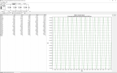
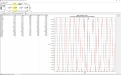
I was curious too, so I ran the sims prior to getting everything together a few weeks ago. PSUD shows directionally that the inductor is best placed as CCLCRC vs. CCRCLC, but it's not necessarily a meaningful difference.
Simmed Ripple with a 3A load - L early is 102uV ... L later is 111uV
Considering my standard CRC supply Sims (and measures pretty closely) to 130mV, I'm sure I'll be happy either way.
Note - that's with adding 33kuF in the amp chassis.
More important note - I have no idea what I'm doing, but I'm giving it a whirl! 🙂
Thanks!
I treat 2 caps in parallel essentially as one for nomenclature, but yes, CCRCRC is definitely more correct, apologies. Great boards!
This is probably not the best thread for it, but I have a suggestion. Similar to the Singing Bush boards you did, if you had some extra, larger through-holes for the larger gauge wires for chokes, it would be a fantastic addition for your next run. Not sure how many people would use them, but... For now, and for me, it's easy enough to wire to the resistor pads.
I was curious too, so I ran the sims prior to getting everything together a few weeks ago. PSUD shows directionally that the inductor is best placed as CCLCRC vs. CCRCLC, but it's not necessarily a meaningful difference.
Simmed Ripple with a 3A load - L early is 102uV ... L later is 111uV
Considering my standard CRC supply Sims (and measures pretty closely) to 130mV, I'm sure I'll be happy either way.
Note - that's with adding 33kuF in the amp chassis.
More important note - I have no idea what I'm doing, but I'm giving it a whirl! 🙂
- I put in what I think are the proper specs for the transformer including the proper resistance and regulation.
- I picked a bog standard bridge that should be close enough.
- Instead of doing CC I used 66kuF with ESR halved for the two caps in parallel. I should run it with CC to see if it makes a difference.
- Tried to enter proper specs for the Inductor including the series resistance
- 33kuF caps for the rest
- I tried to put the motor-run cap into the Sim and everything went absolutely haywire. I haven't figured out what I did wrong (yet).
Thanks!
Post a screenshot of your PSU designer. I would expect much lower ripple at the end of the CCLCRC. I think that’s the right order, btw. The bank in the amp chassis will be the icing on the cake.
Aha. 102uV = 0.102mV. I must have read mV the first time. Just got home from a 450 mile road trip today. Brain isn’t running full speed
You’re going to have an incredible sounding A60 setup
You’re going to have an incredible sounding A60 setup
Last edited:
I hear ya. I just got back home from a week away ... I'm wiped. As a matter of fact... I think it's time for some tunes before crashing out.
Appreciate all the help!
Appreciate all the help!
![IMG_3562[18017].jpg](/community/data/attachments/1097/1097932-2df75e285aad25dd0434286b5525544b.jpg?hash=LfdeKFqtJd)

Looks nice! I'm sure you know this but hit the solder joints on the output MOSFETs with the soldering gun after you reassemble it with the insulators. That should take a lot of the tension out of the leads.
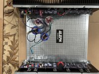
Looking good. What sized chassis are you using?Had a bit of time to do a test fit. It's coming along.
For those that are... I soldered the MOSFETs with the proper thermal pads and torque. I removed the boards for a bit of extra cleaning and test fitting.
Killer project.
Definitely. They were soldered with the insulators in place, and under proper torque (just like final assembly), but I always hit 'em once more when they're in "for good"Looks nice! I'm sure you know this but hit the solder joints on the output MOSFETs with the soldering gun after you reassemble it with the insulators. That should take a lot of the tension out of the leads.
Thanks!Looking great!!!
Thank you! I got a couple of the "Toxic Masculinity" chassis in anticipation of doing big honkin' Aleph monoblocks... I decided that's overkill (for now). It's one of them. The other has my BA-3 in it.Looking good. What sized chassis are you using?
Details are ... Modushop 4U/500 with UMS sinks and a few other mods. It's likely the same as in post #874. Original thread is here.
https://www.diyaudio.com/community/threads/picos-toxic-masculinity-class-a-amp-chassis.362494/
A little more progress.
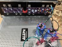
Both boards were checked out with the PSU. I did a quick initial bias to ~2A and zeroed the offset. I have not done anything re: the AC gain. I'll do that when I get the inputs added etc.
Huge shout out to @rhthatcher. It's taken me a while to get started on the project, but it's a fun build. I may have music later in the week. The guide is fantastic, and the boards are a dream to work with.
Note - I will do a little more learning, and I'm sure it's 'normal', but for those out there that are fraidy cats like me and like to ramp up their voltages slowly... I had an observation that initially had me worried.
I put DMMs across a selection of the source resistors during initial power-up to make sure nothing was wonky. I was also monitoring offset and the PSU voltages. Initially, the voltage across (current through) the source resistors was too high. If I recall, it was ~500mV or more. So, I thought to myself, "Self! You're a knowledgeable and good-looking amplifier builder. That's why we power up slowly. Back down on the bias current and move on." So, I backed off the bias current. Yay team. I steadily increased the PSU voltage, and the bias current decreased ... So, I had to crank the bias back up. I don't recall any other amp I've built doing anything like that. If someone has a brief explanation, I'd be grateful.
With a standard power-up straight to full power, clearly this is a non-issue. If some other person that uses a Variac or similar to slowly ramp up PSU voltages sees this ... don't worry... it works.
The cap bank in the chassis is only temporarily wired. I wanted to test it all out and choose a layout before tidying up the wiring.
As always, ideas are appreciated.
Attachments
Alrighty... the madness has truly begun... mwah ha ha...
I had enough confidence in the PSU to use it to start to refine bias / offset and begin the initial AC gain settings. Initial bias/offset went off without a hitch.
I wanted to do as much of it with the lids off... just in case something needed to be taken out... so far, so good; knock wood. I'll refine with the lids on, but ... hopefully it will be minor tweaks.
I have read, and read, and then read even more to try and understand both the Aleph Current Source, and the AC gain. I'm still a bit lacking, and I'd like some help, please.
First... kudos again to @rhthatcher. The guide is truly impressive and 99% dodo proof.
Here's the 1%...
1) How critical is the Vrms at the output? I could squeak 15Vrms when the amp was driven from a phone / baby pre-amp. 16Vrms / 8R is used as an example from Nelson, but I assume lower should be okay... I think this has been covered, but how low is likely to be okay?
2) Expanding on that... when the jumper goes back, the voltage at the output increases; albeit, slightly. Is it expected in the process that we should dial back the voltage to match as precisely as possible to the initial voltage with the jumper in? If so, I've got to re-jigger a few things.
3) At 15Vrms output, I was not able to get the AC gain low enough (voltage across the source resistors up to 50%). I was able to get it roughly to 80% of the target voltage => 40% of the original voltage with the jumper out => 60% AC gain before the pots were at their end-points. (Same on both channels)
4) Since my load resistors were getting quite toasty... I thought I'd try a lower voltage. I tried 4Vrms. I was able to dial in the AC gain to 50% +- 1%. The pots have a bit of travel left.
It seems that the AC gain may vary dependent on the output. Is that correct/normal? Am I interpreting this properly? Can anyone offer any further insight? If so, I'd be grateful. I can provide a ton more information if needed, but I was trying to keep it as simple as I could re: what I observed.
Overall, if the answer is ... setting the AC gain at 4Vrms @ 8R is just fine... move along. I'm willing to take that and run.
Also... is it okay to replace the jumper with the amp under power? Powering down / back up and waiting for any type equilibrium is a bit... of a long process. I think we can pop it back on again w/o a power cycle, but I wanted to be sure. It would be nice to just take the initial readings with the jumper off, then pop the jumper back on and dial P2. Randy's instructions are awesome, and they don't say to power down... but I was cautious.
Thanks!!!!
Edited to add - I found this quote from this post to be very valuable... but still wasn't completely sure about the gain changing with output.
"Actually the figures given by Mr. Pass are just an example. They need not be exact. You just need to produce a signal across the speaker output high enough so that the AC voltage at the source resistors can be measured. What you must do is to keep the input signal the same at all time and the output is not clipped."
https://www.diyaudio.com/community/...t-source-adjustment.38033/page-2#post-1197539
Last edited:
Patrick,
Did you have a chance to read the separate pdf article Randy has written, titled Classic Aleph Gain Setting Procedure? It’s attached to the 1st post of this thread and goes through the procedure along with the changes that can happen with output voltage when removing/installing the jumper. I don’t think you are supposed to shut down the amplifier during this procedure or else he would have mentioned it in the instructions. The Vrms you choose is arbitrary. I would try again at 10Vrms which is about 12.5 watts into an 8 ohm resistor. Post your results here. Since you are such a meticulous builder, I have a feeling you have a good working amplifier 😉 .
Best,
Anand.
Anand beat me to it. See that PDF. Voltage is arbitrary.
Also, don't sweat DC offset until it's warmed up. If you within spec, leave it alone. And if you're using the SFP9610's I sent, you won't need to turn the DC offset pot.
Also, don't sweat DC offset until it's warmed up. If you within spec, leave it alone. And if you're using the SFP9610's I sent, you won't need to turn the DC offset pot.
Hi Anand!
Thank you! Yes, I definitely read that.
It does seem to contradict the quote I pasted in the edit above though, which states that the input signal should not change.
I admit to being a bit confused on all this (and/or misinterpreting)... and it's likely just wonderful as is. Sometimes I get too deep into the weeds.
The question remains though... is the AC gain supposed to change with output signal? I could not get 50% with 15Vrms output, but could get there easily at 4Vrms output.
Edited to add - Randy snuck in there. You're dead on re: the offset. Those things were perfect ... 🙂 🙂
Go for 10Vrms. You will have to twiddle with input when you swap the jumper. The output will dance a little. Very little.
^ Done and dusted!
Sometimes a guy just has to admit that he doesn't understand some things and follow the perfect process put before him...
Back in a flash with good news.

Sometimes a guy just has to admit that he doesn't understand some things and follow the perfect process put before him...
Back in a flash with good news.
This was the most complicated aspect of the Aleph for me to wrap my head around. When I finally got it and made a way to test it I took notes with pix to try to make it easy. I think in the past months I found a post where ZM may have had some simpler way, but I can’t recall where. Once you dial it in, rest easy that you’ve optimized your Aleph and then enjoy some tunes!
color me dumb, but I always got it with two Vac meters, one situated across source resistor of upper mosfet, second one across source resistors of lower mosfet
when readings are equal, same contribution of upper and lower half, thus Aleph AC Gain=50%
applying same logic with some mild use of calc, you can set it to whatever % you prefer
maybe my reasoning is wrong, but I was forced to it, never being able to understand Papa's explanation of procedure, in Yore
heck - I'm pretty sure that now, Pa being in his more laidback/chill phase, even he is outa town, before understanding that old tutorial
Last edited:
- Home
- Amplifiers
- Pass Labs
- Classic Aleph Amplifier for Modern UMS Chassis Builder's Thread