SM opening at 0.1mm is pretty tight, 0.15mm is more common. I see JLCPCB saying that they are capable of 0.038mm, which I doubt but never measured. I know the silk registration is know where near that.
https://jlcpcb.com/capabilities/Capabilities
Fuses on power rails, O/P side, each channel, put on the PS pcb, use 5x20mm fuse ? good enough? Maybe user accessable on the back panel.
Crossbar/control to blow out fuses, disconnect speakers, on a over load, features, decisions, ...
After doing the BC-1 design I learnt, do the mech design first, then the electroinics.
It depends on folks capabilities to fab what you design.
That's the way we did it at HP, the ME gave me a pcb ouline, containing all the mount locations, after we worked out the min possible pcb siz based on the design.
Good luck, got to go help my wife with groceries 🙂
| Pad To Silkscreen | 0.15mm |
Fuses on power rails, O/P side, each channel, put on the PS pcb, use 5x20mm fuse ? good enough? Maybe user accessable on the back panel.
Crossbar/control to blow out fuses, disconnect speakers, on a over load, features, decisions, ...
After doing the BC-1 design I learnt, do the mech design first, then the electroinics.
It depends on folks capabilities to fab what you design.
That's the way we did it at HP, the ME gave me a pcb ouline, containing all the mount locations, after we worked out the min possible pcb siz based on the design.
Good luck, got to go help my wife with groceries 🙂
Last edited:
Sprint does allow .01mm increments . I could do something custom like .13 ... etc.
I want things to look OEM +++ , not like a project - even if it is ...
OS
I want things to look OEM +++ , not like a project - even if it is ...
OS
Interesting JLCPCB "trace to board edge" >.3mm. I had the protect traces on both ops's right on the tolerance of that capability.
Good to go , but I moved them back to .5mm to be safe.
Good to go , but I moved them back to .5mm to be safe.
Its the mech design that makes it look OEM, even if the electronics are crap.I want things to look OEM +++ , not like a project - even if it is ...
1.5mm is probably a better # to useInteresting JLCPCB "trace to board edge" >.3mm
Decisions , decisions ..... After building a few , You kind of know which is right.Fuses on power rails, O/P side, each channel, put on the PS pcb, use 5x20mm fuse ? good enough? Maybe user accessable on the back panel.
Crossbar/control to blow out fuses, disconnect speakers, on a over load, features, decisions, ...
I work in hybrid mode , merging the layout with circuit design.
OS

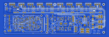
The EF3 boards are final , I uploaded them 3 days ago.
-Mini and full OPS = Standardized everything. This and the big Arcwelder all have 30mm output spacings. One will fit the drillings
of the other.
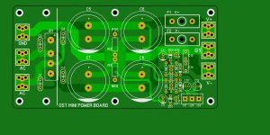
Power board - 15A bridges are SO !! cheap $1.50 - 3$ .... why bother with anything else ? They all have similar lead spacings and pinouts -
(below).
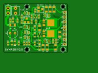
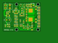
I will upload the power board , SYMASUI (below) and INFIDEL soon.
4 IPS's should be enough diversity to satisfy any audiophile. And the 2 output boards should take care of any speaker system.
My 2.1 will be 2 "mini's and a full Arcwelder in one 400mm X 3U "dissipante" DIYA chassis. Anyone purchase that chassis ?? I'm about
to spend 220$ for one ??
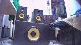
My speakers are waiting !! (below-last)
-Mini and full OPS = Standardized everything. This and the big Arcwelder all have 30mm output spacings. One will fit the drillings
of the other.
Power board - 15A bridges are SO !! cheap $1.50 - 3$ .... why bother with anything else ? They all have similar lead spacings and pinouts -
(below).
I will upload the power board , SYMASUI (below) and INFIDEL soon.
4 IPS's should be enough diversity to satisfy any audiophile. And the 2 output boards should take care of any speaker system.
My 2.1 will be 2 "mini's and a full Arcwelder in one 400mm X 3U "dissipante" DIYA chassis. Anyone purchase that chassis ?? I'm about
to spend 220$ for one ??
My speakers are waiting !! (below-last)
Attachments

I used the 3Ux300mm for the BC-1 amp build, with a bottom pierced plate, Steel, black, 10mm aluminum front.
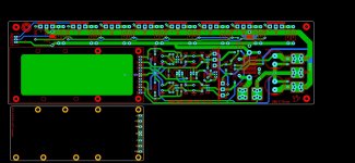
I also designed a AC inlet pcb that mounts to the back and bottom plates. It has IEC socket, switch, fuse, ground isolation,soft-start ckt.
Bought directly from hifi2000, not from DIYAudio store because I do not get free shipping, outside of the US.
I also designed a AC inlet pcb that mounts to the back and bottom plates. It has IEC socket, switch, fuse, ground isolation,soft-start ckt.
Bought directly from hifi2000, not from DIYAudio store because I do not get free shipping, outside of the US.
Last edited:
That dual footprint on the PS pcb used for Ac in, dc out, uses I assume either a quick connect spade or keystone 6-32 screw (7775) for binding a solder lug? the footprint for the 7775 needs a hole in the middle, I used 145mil, look at the detail in the keystone catalog
Last edited:
Thank you ,Rsavas. I just used the (Wolverine teams) 7775. Keystone 7775 does need the hole. There is a HD one (7791) that is taller with no hole.
I'm surprised the wolverine macro is not updated.
Lucky I did not copy many wolverine "features' , errors....
I have the sheet , https://www.keyelco.com/userAssets/file/M65p67.pdf
I'll make new macro's. I still want any PCB to take 2 faston's , as well.
OS
I'm surprised the wolverine macro is not updated.
Lucky I did not copy many wolverine "features' , errors....
I have the sheet , https://www.keyelco.com/userAssets/file/M65p67.pdf
I'll make new macro's. I still want any PCB to take 2 faston's , as well.
OS
If you will wait . I AM going to submit the through-hole spooky here.hello otripper, can i do this? , I like this like this
My next upload will be , TH spook , Infidel , and Symasui.
OS
Wolverine template fits my small SMD boards , but the full size is now 122mm , with different holes.
Sucks having to change my big board to make it "wolverine compatible". I originally designed and set the standard template.
It was changed in my absence. Look at all those holes !!! (below).
I'm not going to make through-hole IPS's (except for the spook) ... I already had that artwork done 3 years ago.
Attachments
Wolverine has 36-8191-ND (keystone) , current PCB footprint is right , does not need a hole.
OS
OS
I did "backport" the 5 pair Arcwelder to a 4 pair 76mm tall version , that is what is posted now. If you like the 5 pair , I don't support it.hello otripper, can i do this? , I like this like this
I went with the 76mm 4 pair , as it will do a 3U heatsink and has standard 30mm output spacing. Mini" has 30mm spacing ... one could
upgrade from a mini to the full without messed up holes.
BTW , the 5 pair is the same as the mini or 4 pair in every way.
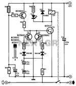
Here , (below) .... I will also offer a SMD protection board. Someone on the Wolverine thread uses this. I DO see one weakness with the simple
DC detect - it won't detect a negative DC fault (R1 + C1 ... below 1). Too slow , no negative , cap too big.
(below 2 - would be a better trigger) . Smaller caps , will do +/- faults , Can run through the same opto.
Lot's of options with a MCU controlling the amp , such as adjustable turnon .... even crowbarring the PS.
The rest of the circuit appears quite good , the Wolverine builder even ported it to match the "protect" jack on the OPS and
he triggers his SMPS into fault mode with it. Real easy and cheap to do in SMD form.
OS
Attachments
Okay, good to check, 8191 is different footprint, higher profile, no center hole required.
I like 7775 since the screw is capative, binds upon withdrawal, so will not fall out.
I like 7775 since the screw is capative, binds upon withdrawal, so will not fall out.
It is very important to do this , since it will likely be my own money (he he) , NO mistakes.
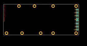
The mini OPS was perfect , now the big 4 pair one will take a wolverine board. I will stick with the 8191 standoff , it seems to of been
chosen because it is soooo common , Digikey has 131K in stock !
Below is the wolverine template for the big boards . I left pilot holes for all the weird holes and the main PCB corner hole is the far
left hole to support a 122mm (weird) size. All my SMD IPS's fit in the 4 right holes and the mini just aligns the first 2 right holes.
OS
Attachments
There is a few points of attention with the mentioned design.Here , (below) .... I will also offer a SMD protection board. Someone on the Wolverine thread uses this. I DO see one weakness with the simple
DC detect - it won't detect a negative DC fault (R1 + C1 ... below 1). Too slow , no negative , cap too big.
(below 2 - would be a better trigger) . Smaller caps , will do +/- faults , Can run through the same opto.
Lot's of options with a MCU controlling the amp , such as adjustable turnon .... even crowbarring the PS.
The rest of the circuit appears quite good , the Wolverine builder even ported it to match the "protect" jack on the OPS and
he triggers his SMPS into fault mode with it. Real easy and cheap to do in SMD form.
OS
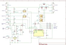
- It does not provide a procedure for a toroidal transformer soft start.
- DC protect is not handled by an interrupt.
- It uses the Delay() Function, which will render the ATtiny unresponsive to anything else until the delay is finished.
- It cant be updated in circuit.
I agree , it is too simple. Needs a lot of work. Might not use it.
Or just use parts of it.
I think he just used it for his SMPS , custom designed it just for his purposes.
I'd rather have a circuit that uses a full ESPxxxx (with wi-fi).
As far as soft-start , there are mini MOV boards .... or resistive delay circuits that can take care of this.
The "mini" and it's smaller PS most likely won't need a soft start. The Big OPS's will.
OS
- Home
- Amplifiers
- Solid State
- Spooky and Hellraiser SMD 60W amps (Wolverine compatible IPS)