I could use my current active analog crossover to cross woofer and midbass horn and time align mid-high and high horn on the mid bass.
Taking this a step further I wonder if it is really necessary to time align a tweeter crossed at 5Khz or if a simple 2nd or 3rd order passive filter will do. The mid-high horn delay is about 1ms on the tweeter so audibility is questionable/boarderline. Of course the midbass horn has 4ms delay on the tweeter but they are spaced more than two octaves apart.
This could further reduce the DSP outputs to 4 and only two tube amps, as I am planning to use a solid state amp on the woofer in any case.
Perhaps I could get away with a Frankenstein system (active-DSP-passive), with two tube amps and one S.S.
For sure this could be evaluated with a 3 ways DSP, but something tells me my aging ears won't feel no difference and will confirm Paul Klipsch experiment.
https://audiosciencereview.com/foru...me-alignment-does-it-matter.13849/post-423170
Use of the loudspeaker wizard in to Tools menu would help with Q 1 and 2. Inputting the path distance (between speaker and terminus) and some filling will make a smoother response versus some bass roll off and gives an idea of the amount of filling to experiment with. Q2 Sorry I do not know for certain the absolute levels but there are opinions out there. You could simulate a range of enclosure types using the HornResp Input Wizard, considering use as a subwoofer and check which response looks best compared to size etc. Or if you go with a TL, are you happy with the enclosure dimensions and where folds will end up.1. How to ensure that the excursions are within Xmax?
2. What is the safe air velocity at the terminus of the TL?
3. What are the final check points to be enured before committing the design on wood?
Also, please suggest if there are any better alignments possible for this driver.

Well, 1 ms = ~1.13 ft, so based on this interactive hearing chart and IME back in the late '60s - mid '80s using my then youthful female's acute hearing it is, though not me and my already damaged hearing from a wide range of high SPL sources, i.e. YMMV, etc..Taking this a step further I wonder if it is really necessary to time align a tweeter crossed at 5Khz or if a simple 2nd or 3rd order passive filter will do. The mid-high horn delay is about 1ms on the tweeter so audibility is questionable/boarderline.
@GM, I am discussing sensitivity to group delay.
Comparison of the previously reported group-delay thresholds (gray lines) and the results of the latest study (black curves).
The results indicate that the audibility thresholds for local group-delay variation are less than ±1 ms for the most critical signals, and approximately 1.5 ms to 4.5 ms for a local positive group-delay peak and between −1.0 ms and −2.3 ms for a local negative group-delay peak for real-life signals.
There is no report for frequency below 500Hz in the more recent study, however based on previous studies the threshold at 200Hz is probably above 5ms.

The study can be downloaded at this link
Based on this study I am questioning the actual requirement to address Group delay by means of DSP or allpass filters in the described scenario with the following GD figures, which are either below or on the edge of the threshold.
Direct Radiation Woofer: 0 ms
Midbass horn xover @200Hz: -4 ms to woofer
Midhigh horn xover @900Hz -1 ms to woofer
Tweeter horn xover @5000Hz +0,2 ms to woofer
Comparison of the previously reported group-delay thresholds (gray lines) and the results of the latest study (black curves).
The results indicate that the audibility thresholds for local group-delay variation are less than ±1 ms for the most critical signals, and approximately 1.5 ms to 4.5 ms for a local positive group-delay peak and between −1.0 ms and −2.3 ms for a local negative group-delay peak for real-life signals.
There is no report for frequency below 500Hz in the more recent study, however based on previous studies the threshold at 200Hz is probably above 5ms.
The study can be downloaded at this link
Based on this study I am questioning the actual requirement to address Group delay by means of DSP or allpass filters in the described scenario with the following GD figures, which are either below or on the edge of the threshold.
Direct Radiation Woofer: 0 ms
Midbass horn xover @200Hz: -4 ms to woofer
Midhigh horn xover @900Hz -1 ms to woofer
Tweeter horn xover @5000Hz +0,2 ms to woofer
Last edited:
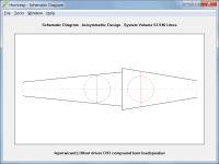
I'm not sure what you mean by hybrid bandpass-transmissionline, and I definitely don't understand what the "like this" example is showing 🙂.is it possbile with Hornresp to simulate a hybrid bandpass-transmissionline?
Somehow like this:
Looking at my post, i don't understand it either ;-) I tried to sketch it with ascii, but the code-block somehow made a linebreak it seems.I'm not sure what you mean by hybrid bandpass-transmissionline, and I definitely don't understand what the "like this" example is showing
I meant something like the sketch below, a 6th-order bandpass with transmissionlines as vented enclosures.
A 4th-order bandpass with a transmissonline might also be interesting.
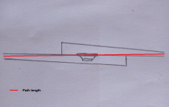
Maybe ‘Ch3‘ mode with ‘path’ set at the distance between vent exits?Looking at my post, i don't understand it either ;-) I tried to sketch it with ascii, but the code-block somehow made a linebreak it seems.
I meant something like the sketch below, a 6th-order bandpass with transmissionlines as vented enclosures.
View attachment 1174812
A 4th-order bandpass with a transmissonline might also be interesting.
I meant something like the sketch below, a 6th-order bandpass with transmissionlines as vented enclosures.
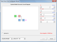
As Booger weldz has suggested, use the CH3 configuration shown in Attachments 1 and 2, with the path length being the distance between the two outputs as shown by the long red line in Attachment 3.
A 4th-order bandpass with a transmissonline might also be interesting.
Use the OD configuration with rear chamber, as shown in Attachments 4 and 5.
Attachments


Hi everyone.
I am trying to simulate MLTL with Hornresp and I noticed something strange is happening. When I go to: Tools, Options, Throat chamber and rear chamber resonances and change from Not masked to Masked or prompt or any other change, it seams that Hornresp disregards it and masks resonances randomly. Further, if I go to : Tools, Laudspeaker Wizard and select Power, resonances are always masked regardless of previous setting.
My Hornresp is installed in C/Hornresp and I tried this on two other PC-s, all Windows 10, with same issue. This is only happening when I try to simulate MLTL, works fine if I simulate BLH for example.
I would appreciate if someone could tell me if I am doing something wrong or maybe there is an issue with Hornresp or something else.
I have attached Hornresp export record that I have issues with.
Thanks.
Attachments
I am trying to simulate MLTL with Hornresp and I noticed something strange is happening.
Hi Zemljan,
Thanks for the feedback, you have indeed found a bug!
QL is inadvertently being set to Lossless when the Resonances Masked option is changed. This will be fixed in the next update.
Kind regards,
David
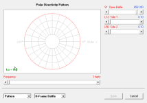
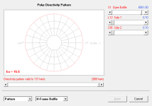
Is this a bug in the polar directivity pattern? Even for a flat baffle, I see no dipole cancellation and behaves as a monopole at all frequencies.
Hi Giri,
It is not really a bug, just a limitation of the model. I have managed to find a way around it though, and it will be changed in the next update.
Kind regards,
David
As Booger weldz has suggested, use the CH3 configuration shown in Attachments 1 and 2, with the path length being the distance between the two outputs as shown by the long red line in Attachment 3.
Use the OD configuration with rear chamber, as shown in Attachments 4 and 5.
Thanks very much for this info.
A question ab mouth velocity and compound horn: There are two mouths, but only one mouth velocity. Does this show the peak velocity, no matter on which mouth it occours?
Although not clear from the heading, the horn mouth peak particle velocity chart in the compound horn loudspeaker wizard currently only shows the results for Horn 1, regardless of the selected power output setting. This will be changed in the next update so that when Output 2 is selected, the results for Horn 2 will be shown instead and the heading will indicate this.
In the meantime, the Horn 2 mouth particle velocity option can be selected from the main results window as follows:
1. Calculate the acoustical power response.
2. Select menu commands Tools > Output > Horn 2.
3. Select menu commands Tools > Particle Velocity > Horn 2 Mouth.
In the meantime, the Horn 2 mouth particle velocity option can be selected from the main results window as follows:
1. Calculate the acoustical power response.
2. Select menu commands Tools > Output > Horn 2.
3. Select menu commands Tools > Particle Velocity > Horn 2 Mouth.
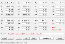
After fiddling around with CH3, i came to this FR, grey line is 1w, red is 15w:

I'm surprised how loud this is from 40-200Hz for a 5" woofer, and safe to use under 35Hz.
If i build this in a down-firing enclosure and put it in a corner, is it really expected to put out this FR
in the room, so i could x-over at about 200Hz?
I'm surprised how loud this is from 40-200Hz for a 5" woofer, and safe to use under 35Hz.
If i build this in a down-firing enclosure and put it in a corner, is it really expected to put out this FR
in the room, so i could x-over at about 200Hz?
In Theory if specs are accurate, though depends on how rigid/massive the corner/room construction is, i.e. in my old cheaply built house for Southern USA climate it takes two corners loaded to make one corner loading in a modern concrete slab foundation, concrete/brick house for Northern climates.
Thanks for your feedback, so if i compensate somehow enclosure/corner losses(lower frequencies get more lost i assume) it might work.
If the mouth velocity peak is well under 10m/s, does the mouth port aspect ratio still matter in a tapered horn regading port noise or tuning of the horn? I mean, it is not a slot with a constant area. Might i use a 20:1 ratio rectangular mouth without issues?
If the mouth velocity peak is well under 10m/s, does the mouth port aspect ratio still matter in a tapered horn regading port noise or tuning of the horn? I mean, it is not a slot with a constant area. Might i use a 20:1 ratio rectangular mouth without issues?
@GM, I am discussing sensitivity to group delay.
Be careful to not confuse group delay with propagation delay. If the sensitivity for group delay is 2ms, and the sound source is 10m away, there is a delay of about 30ms. Will this be audible? Does the 2ms limit mean that you should sit closer than 70cm from your speakers? No. Group delay is a way to describe how, popularly speaking, some frequencies are more delayed than others, and is a result of phase shifts. Group delay will sound more "phasey" while different propagation delays between different units sounds more like there are several sound sources, not one coherent source. It's a bit hard to describe, but they are not the same. So I don't think you can use group delay audibility studies directly to judge the audibility of speaker drivers with different propagation delay.
- Home
- Loudspeakers
- Subwoofers
- Hornresp