F5Turbo has 50 plus watts and most of it class A. With the F5 s gain of about 15 I think B1 would be able to drive any speaker to the limit.
I do not think you will need a sub.
If you are using full range singledrivers as your speakers you can try a passive sub with stereo inputs like I have done.
There are many who use F5 & the F5T with the B1 and it would be interesting to hear what they have to say about the bass.
First build both, couple them and lets see what else we could come up with.
Hello, I'm agree with srian, I build some Weeks ago the B1 buffer and Works fine with Aleph J and F5, in fact I can say I listen the low freq more when it's sounding at low level. It's only based on my experience, but with my speakers, 2 way 21 litre monitor satori and 5.5 excel + millenium in a small and medium room, about 8 and 18 square meters.
What speakers are using ? With the current of the F5 my smallest monitor scan speak revelator 15w with 7 liters cabinet sound like a monster.... and don't need to add a sub for music, maybe for cinema yes, what are you looking for ?
What speakers are using ? With the current of the F5 my smallest monitor scan speak revelator 15w with 7 liters cabinet sound like a monster.... and don't need to add a sub for music, maybe for cinema yes, what are you looking for ?
I've already got the sub, an SVS SB2000 Pro, really wonderful unit. For me the sub is about impact and extension. My HiVi 3.1s go to maybe 40hz, but my SVS can do ~14hz in this room. I use these in a nearfield setup. The F5T I'm building will be replacing an SMSL SA300 in this setup. I'm using an A90 as both a headphone amp and a preamp currently, just looking into the idea of building a B1 as an upgraded preamp. When I replace the SA300 with the F5T I will lose my current mono-mixdown sub out. I'm happy to split the output before the F5T, or worst case put my sub between the preamp and F5T using the sub's buffered throughs, but if I could easily add a sub out to one of the B1's outputs that would be ideal. I appreciate that both of you weighed in about sound quality and the need for a subwoofer in my setup, but I'd love some input on my actual questions. Is adding a sub out as easy as described in the site I linked above? Is there a better way to do it? And if I build a balanced B1, I could have one or more unbalanced outputs, I would just ignore the inverted channel, or perhaps send it to ground through a resistor? Thanks!
Verticalmammel
Do this experiment.
Build the b1 with individual volume controls to left and right channels.
Feed the left chanel output of b1 to the f5t and the right out to the svs sb 2000pro.
The f5t will have both speakers connected but will play music only on the left speaker.
Listen.
If you like the result build another b1 in the same box and repeat the process to the other chanel.
Any more suggestions out there please?
Input and output questions
I apologize if this is simply answered in this thread - since it is huge, it's hard to find a definite answer.
1. I want to just build a simple buffer without volume control - I will play around with a diy Magnequest Ingot, a Lighter Note LDR, and/or an external pot/stepped attenuator (and maybe a Slagleformer too.) Are the 1Meg resistors sufficient, or do I need to add a resistor in the place of the volume pot on the board. And which pads on the board do I use for input?
2. Output resistor- I see in this thread recommendations as low as 22R to 51R, or even omitting it entirely. I would like as low an output impedance as possible, to drive multiple amplifiers and/or long cables. What should I use? And should I stick with the 10uF output cap, or change that?
Thanks in advance!
Insted of 25k pot have a 25k resistor to gnd. Upper end of this resistor connected to the input / 1k restor (R202) junction. B1 will receive full signal and output 95% of it. Leave 10uf cap so that there will not be any dc offset in the output signal specialy when you switch off the B1.
Use any fancy resistor from 22r to 1k at the output. Connect your external attenuator of yout choice and experiment. The impedance value of this attenautor only will load your power amplifier device.
Experiment freely and find most suitable value for resistor and attenuator.
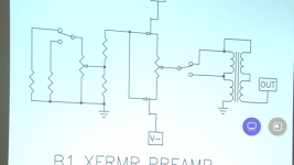
Begin with standard values of 51r for R204 and the attenuator value used in the light speed attenuator somewhere in the thread for the B1. Best sonics could be obtained if you use transformer
Attenuator for the B1 as suggested by Doctor Pass.
The link I have given in a previous post close to this #.
Use any fancy resistor from 22r to 1k at the output. Connect your external attenuator of yout choice and experiment. The impedance value of this attenautor only will load your power amplifier device.
Experiment freely and find most suitable value for resistor and attenuator.
Begin with standard values of 51r for R204 and the attenuator value used in the light speed attenuator somewhere in the thread for the B1. Best sonics could be obtained if you use transformer
Attenuator for the B1 as suggested by Doctor Pass.
The link I have given in a previous post close to this #.
Attachments
My B1 journey experience according to best sonics
1. 25k vol pot at input. Good.
2. 25k ladder attenuator at input. Better.
3. No control at the input, only 1k and a 25k resistors as explained above.
But my own tvc volume control at the output. Best sonics.
Better bass. Also have gain from the tvc. 100r resistor used at the input of tvc to
prevent loading the fets.
I've been using the B1 for a few years and I really enjoy it.
I was posting a question on another forum about the cap C201/101. A few of the more knowledgeable guys read the schematic and said the 10uf cap should be more like around 1.2uf.
I use this for both a tube amp (high impedance input) and a solid state vintage Marantz 250m @100k input impedance.
Is this true or just an engineering argument. Honestly, I trust Pass's design more than a posting reply.
Having been playing around with the new KT150 integrated tube amplifier and some other Hi Fi integrated amps for some time, came back to test my new TQWT speaker design made with fullrange Fostex 206EN, I had to switch on the PASS B1 with a 100 watts Technics power amplifier made with bridged mode STK050 power ic's.
Can't believe what I've heard!
Better than anything I have heard!
Pass B1 is simply addictive if hooked up and listened to with other good equipment in your audio set-up.
Can't believe what I've heard!
Better than anything I have heard!
Pass B1 is simply addictive if hooked up and listened to with other good equipment in your audio set-up.

Im currently using a B1 Nutube for preamp and wanted to try the B1 by itself. I've been struggling with the BOM though, will this be right? Im planning on getting the PCB+JFETS from PassDiy.
the only thing Im not able to find is the 25k potentiometer. I've been using a 50k log for my Nutube, will that work?
Ill be powering a Hypex NC400 stereo amp
| Q | TYPE | VALUE | Digikey Part Number | |
| RX00, RX01, RX03 | 6 | R | 1/4 1M | RN60C1004FRE6 |
| PX00 | 1 | POT | 25K | - |
| RX02, RX04 | 4 | R | 1/4 1K | CMF501K0000FHEA |
| C3, CX00 | 3 | C | 1UF | BFC241671005 |
| CX02 | 2 | C | 10UF | PHE426HR8100JR06L2 |
| RX05 | 2 | R | 1/4 221K | CMF50221K00FHEB |
| R2, R3 | 2 | R | 1/4 10K | CMF5010K000FKEB |
| C1, C2 | 2 | C | 15000 25V | UFW1E153MRD |
| R4 | 1 | R | 1/4 15K | CMF5015K000FHEB |
| D1 | 1 | D | 1N914 | 1N914TR |
| D2 | 1 | D | LED | WP113IDT |
| R1 | 1 | R | 3W 1 | CPF31R0000FKE14 |
the only thing Im not able to find is the 25k potentiometer. I've been using a 50k log for my Nutube, will that work?
Ill be powering a Hypex NC400 stereo amp
Try searching ebay for a PEC 25k potentiometer to see what results you get.
Then again, in his article Nelson says, "The potentiometers are linear taper at 25 Kohm, but again you can easily use higher or lower values as you like." So you should be able to use your 50K pots instead. (Emphasis mine.)
Then again, in his article Nelson says, "The potentiometers are linear taper at 25 Kohm, but again you can easily use higher or lower values as you like." So you should be able to use your 50K pots instead. (Emphasis mine.)
Last edited:
I recently completed my version of the the B1 buffer. I wanted a two channel buffer without volume control. But I wanted to switch the inputs via a tacticle switch on the front panel. I added a 5V supply to the build which powers a PIC. The PIC handles switch debouncing, front panel LED indicators and input switching via 5V relays. The build sits in a Breeze 1907 enclosure from AliExpress, PCS are from Seeed studio, and panel machining/engraving by Shaeffer AG in Berlin.


Hello diyFriends!
As I‘m finally finishing my B1 I have a question to the engineers here:
I will use a Wall Plug style Power supply. (Because Mr. Pass says so ;-))
Everything will go into a metal housing (hifi2000 galaxy series). Do I connect the housing to GND which is basically the “-“ lead on an isolated power supply since they don’t have a GND connection or do i mount the pcb and all the components isolated on nylon standoffs with no connection to the housing??
I can’t quite wrap my head around that because all my other devices (DAC, Phono Pre, TT) are on isolated Wall PS also with my active speakers being the only component with a grounded power supply.
I guess that everything has the potential of the power speakers through the neg signal wire, right?
Therefore, do I leave the housing afloat or do I connect it to the “-“??
- Home
- Amplifiers
- Pass Labs
- B1 preamp build thread