The input impedance of the MC stage is affected by the base impedance of the two input transistors. For noise reasons you want that to be as low as possible hence the 220uF. If you have a low ESR cap, then I would use it.
That makes perfect sense and I understand what you mean now, you went with a 220uF cap as the ESR is lower, and the ESRThe input impedance of the MC stage is affected by the base impedance of the two input transistors. For noise reasons you want that to be as low as possible hence the 220uF. If you have a low ESR cap, then I would use it.
Resistors are correct and I replaced the caps, offsets are the same as before. Can a bad HFE match on the transistors be a cause of this? The other one I built I used BC550C/BC560C and it was perfect. ThanksAlso, check the associated bias resistors R23 and R24.

Swapped out the transistors for that channel with BC327-40/BC337-40 to test and now the offset is at 12mV, looks like too much of a mismatch with the other ones ( 30hfe difference ).
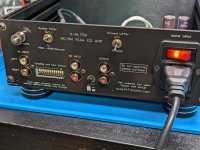
Also Black sharpie works great for the PCB edges on the rear panel so they match the housing too.
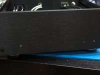
What I did for the LED's was I only drilled a 1.5mm hole through, then drilled the LED pilot leaving about 2mm of material to the front. Just gives a nice light glow to indicate its on 👍
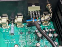
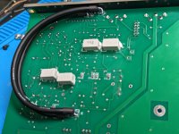
I used CAT6a stranded and shielded for the filter switch wiring, and then grounded the shield at the back panel end.
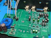
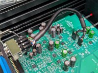
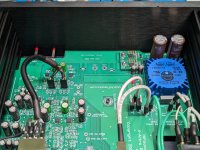
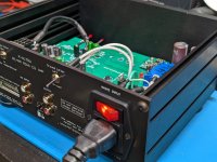
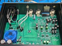
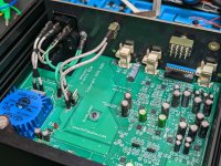
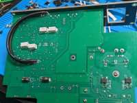
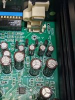
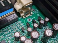
Build Pics attached.
Also Black sharpie works great for the PCB edges on the rear panel so they match the housing too.
What I did for the LED's was I only drilled a 1.5mm hole through, then drilled the LED pilot leaving about 2mm of material to the front. Just gives a nice light glow to indicate its on 👍
I used CAT6a stranded and shielded for the filter switch wiring, and then grounded the shield at the back panel end.
Build Pics attached.
Attachments
-
 PXL_20230414_191952041.jpg518.6 KB · Views: 342
 -
 PXL_20230417_184151994.jpg289.3 KB · Views: 311
 -
 PXL_20230417_184108130.jpg424.7 KB · Views: 319
 -
 PXL_20230417_184041651.jpg524.3 KB · Views: 308
 -
 PXL_20230417_184032821.jpg499.1 KB · Views: 313
 -
 PXL_20230417_184021073.jpg355.6 KB · Views: 296
 -
 PXL_20230417_184013268.jpg404.5 KB · Views: 319
 -
 PXL_20230414_205601794.jpg542.8 KB · Views: 333
 -
 PXL_20230414_205553531.jpg539.4 KB · Views: 309
 -
 PXL_20230414_191955889.jpg497.4 KB · Views: 294
 -
 PXL_20230414_192035464.jpg374 KB · Views: 293
 -
 PXL_20230414_192049622.jpg300.9 KB · Views: 292
 -
 PXL_20230414_205454847.jpg558.8 KB · Views: 283
 -
 PXL_20230414_205511028.jpg563.6 KB · Views: 322
ok - looks like you have a large Vbe and a large hFE difference between the N and P devices on that channel. I any case, the servo will remove this. I will suggest for future builders that they use the closest matched N & P pairs together in each channel to minimize any potential initial offset.
Have you flashed U28 and U29 closed and checked that the input offset goes to 0.00mV? You have to measure right at the input connector because there is a small DC voltage drops across the ground that will affect the reading.
Fantastic looking PCB build 👍
Have you flashed U28 and U29 closed and checked that the input offset goes to 0.00mV? You have to measure right at the input connector because there is a small DC voltage drops across the ground that will affect the reading.
Fantastic looking PCB build 👍
I haven't yet I was lucky enough to source some NOS ZTX951 and mouser has ZTZ851 now so I will replace those transistor pairs first. I only installed to test the offset.Have you flashed U28 and U29 closed and checked that the input offset goes to 0.00mV? You have to measure right at the input connector because there is a small DC voltage drops across the ground that will affect the reading.
Thanks, and really the compliments should go to you Andrew for this amazing piece of kit!
Couple updates. I replaced right channel transistors now with a matched pair of ZTX951/851 and the resulting offset is 1.5mV. Attached are both pairs curve traced for comparison. It was the mismatch causing that issue.


I also decided to order a handful of different caps to measure out of curiosity for C9,C10,C24,C25. I will post the ones of most interest. 2.5mm X 6.3mm caps fit with no issue. ESR was taken at 120Hz
First off is the BOM cap.
ECA-0JM221 - 214uF 1.22 ohms
Low Leakage Caps.
UKL1A470KDDANA - 48uF 2.30 ohms
UKL1A101KEDANA - 97uF 1.18 ohms
UKL1A221MPD - 220uF .60 ohms **Too Large to Fit, could be mounted 2 Top 2 Bottom
Best ESR 220uF Cap
EEU-FR0J221B - 195uF 440 mOhms
Best ESR that fits footprint
EKZM6R3ELL471MF11D - 449.2uF 180 mOhms
Testing the leakage current there was quite a noticeable difference with the "Low Leakage Caps" vs the rest, but in the end I decided to use the lowest ESR cap that would fit the board.
Correct, or else there is a larger offset like you have said. OPA2189 is what I am using. My other one with the BC550C/560C is the same around 200uV
Ok. I was never able to resolve accurately down to those levels. At 200 uV you won’t get any issues with your cartridge. Looks like you are good to go.
Ok thats what I thought too, with a handheld DMM its basically 0, I can only measure that with my 6.5 digit. Now onto testing 👍
I could not get those from Mouser to test that would fit the footprint, so I grabbed a couple other Nichion to testMay i suggest trying out nichicon UHW, those are the lowest ESR caps i know of.
UVZ0J221MDD - 207.5uF 1.49 ohms
UKW0J331MED - 278.6uF 1.00 ohms - Don't measure the best, but by far the best looking, Matte Black and Gold!
https://eu.mouser.com/ProductDetail/Rubycon/6.3ZLJ220M5X11?qs=T3oQrply3y8ms%2BWOKJfKlQ==
Then this might be a total hit, rated 400mOhm, 220uf, D=5mm 🙂
Looking at the latest uhw datasheet, they might have pulled production on D=5mm caps (**at those values). Which is too bad for specific use cases like these. UHW are one of my fav's, amazing caps.
Then this might be a total hit, rated 400mOhm, 220uf, D=5mm 🙂
Looking at the latest uhw datasheet, they might have pulled production on D=5mm caps (**at those values). Which is too bad for specific use cases like these. UHW are one of my fav's, amazing caps.
Finally got some time to get around to measuring the X-Altra phono preamp, before I get it hooked up in my system for a listen. If anything looks out of place there is a good chance it might be me, this is really the first time running measurements on a phono preamp. @Bonsai if you see anything suspicious please let me know. From what I can tell, it meets and exceeds published specs.


Right Channel suffers from less main induced noise and hum, which could just be my wiring layout, but overall it is very clean.


Almost a mirror image between channels with a mismatch of around 0.04dB @ 200Hz, and amazing RIAA conformance.


I just want to say thanks to @Bonsai for creating such an amazing phono preamp and sharing it with the DIY community!
First up is the idle noise floor of the measurement chain in loopback
Noise Floor of Left and Right Channels MC and MM inputs
Right Channel suffers from less main induced noise and hum, which could just be my wiring layout, but overall it is very clean.
Left and Right Channel Frequency Sweeps
Almost a mirror image between channels with a mismatch of around 0.04dB @ 200Hz, and amazing RIAA conformance.
1 kHz FFT's MC / MM
1 kHz THD+N vs Generator Level
Overload Margin
I just want to say thanks to @Bonsai for creating such an amazing phono preamp and sharing it with the DIY community!
Thanks for doing these measurements Andy - good to have an independent set to compare against. I am out of town until mid-next week but will take a look at them then
👍👍👍
👍👍👍
- Home
- Source & Line
- Analogue Source
- Bonsai’s X-Altra MC/MM Phono Preamp