Yes.Steve,
I agree in principal with moving microphone concept. And it works if you use noise and an averaging RTA for the measurement. But many people normally use the frequency sweep mode in REW for frequency response measurements. Such a measurement gives a lot of detail like distortion, impulse response, wavelet spectrograms, etc, that you can't get from the moving microphone/RTA method. And, it calculates the filters needed for DSP adjustments automatically. I don't think REW can do that using the results of a moving mic/RTA measurement. (Can it?)
But if you try moving the mic during a REW frequency sweep test, you don't average the results, rather, you just get a result where the response at each frequency is from some random position, which is obviously not what you want.
So I think the averaging of multiple sweep measurements makes sense from the standpoint that you can (I think) average the results and let REW derive the dsp filters from the average. (Somebody correct me if I wrong, I don't have/use DSP myself).
Probably it would be good practice to follow up with a moving mic/RTA measurement to double check the frequency response after making any dsp corrections.
Eric
- MMM is with pink noise and RTA. Don't use it in a sweep mode.
- As I was also afraid to loose time information, I have develop a method of multi point short sweeps... instead of a continuous movement as in MMM, I used short stop waiting for each sweep to finish... but it hasn't lead me to conclusion. The method works but the point is what to do of the information. Which averaging? All of that is linked to the auditory system. A bit complex.
- I am not sure how the correction systems use the time information. One of them is based on frequency dependent window so MMM is not ok for such a correction. i don't know for REW.
Not forgetting gravy and churches.What about very small rocks, did anyone try that? Very small rocks will float, according to the witch scene from Monty Python.
Hello Paul,I would expect low density to assist at HF with compressive strength and damping held constant.
Hmm, not so sure... density is directly in the mechanical impedance which itself in the low pass filter with the moving mass of the simplified model of DML. My current experiments go also in this direction. The point is it is difficult to separate density from compressive strength. Need more experiments?
Could you please remind to everybody the material of the EAR membrane? Its areal density?But, can you even go there with DAEX25CT 10W exciters?
And, it'll be a Study of DML as a Full Range Speaker for the elderly. 🙂
The panel is not the main problem here, but the exciter. That's why the commercial DML makers make pupose-built exciters for their products. Those exciters are not for sale to the general public.
AER also is a DML maker, claims their exciters reach 40-30000hz.
The AER bbx exciter just touches the panel only at one point.
I can say by experience that a 1mm Balsa so thin and light, but not really stiff has no HF.will the driver itself produce decent HF when the VC is connected to a thin, stiff, light panel? Probably yes.
Thanks Eric for your observations. I'm currently trying the moving microphone method in REW. Moving the mic very slowly across the possible listening positions over the width of a 2 seater couch, I get anything from 80 to 100 measurements that are averaged. This average reading can be saved as an REW measurement file that's exactly the same as the file type from a frequency sweep measurement. This average reading can then be used to help generate the PEQ filters. I plug the filter settings into my miniDSP HD in exactly the same way.Steve,
I agree in principal with moving microphone concept. And it works if you use noise and an averaging RTA for the measurement. But many people normally use the frequency sweep mode in REW for frequency response measurements. Such a measurement gives a lot of detail like distortion, impulse response, wavelet spectrograms, etc, that you can't get from the moving microphone/RTA method. And, it calculates the filters needed for DSP adjustments automatically. I don't think REW can do that using the results of a moving mic/RTA measurement. (Can it?)
But if you try moving the mic during a REW frequency sweep test, you don't average the results, rather, you just get a result where the response at each frequency is from some random position, which is obviously not what you want.
So I think the averaging of multiple sweep measurements makes sense from the standpoint that you can (I think) average the results and let REW derive the dsp filters from the average. (Somebody correct me if I wrong, I don't have/use DSP myself).
Probably it would be good practice to follow up with a moving mic/RTA measurement to double check the frequency response after making any dsp corrections.
Eric
For individual driver PEQ, I usually create them manually rather than get REW to do them automatically. This is because the uncorrected driver responses from the open baffle bass and DML panels are very 'lumpy'. Once the bass/DML responses have been broadly corrected (typically within a couple of DB of where I want them to be across their respective responses, I then correct for the bass/DML as a single entity (called Input PEQ in the miniDSP) to smooth out minor peaks & troughs and to set an overall response 'flavour'. I tend to favour a steady drop totalling 3db from 40hz all the way up to 20khz.
Well, if it is about AER bbx exciter, how it is made and its specifications are a business secret. They don't appear to patent their "invention." All I could find was just advertising jargon. But,Could you please remind to everybody the material of the EAR membrane? Its areal density?
That exciter is quite expensive for a DIY project! 🙂
That's why the distributed mode emitter is the most important part of the loudspeaker.
One of the reasons, why put that question, #9,027
Oh, I don't have an answer to that, yet. 🙂
Last edited:
PwayNice. I am interested to see the I uncorrected curve, the correction curve and subwoofer curve (presumably you are using subwoofer)? What DSP setup are you using? What is the mic distance from speakers and how big are the speakers?
Actually, while we are on the topic of EQ, I’m thinking that using one of the current series of Pioneer or Onkyo home theatre systems with Dirac live is probably the easiest, cleanest way to build systems with active crossovers, sub crossovers and EQ. Anyone have experience of these? Sound quality would measure worse than hifi units, but I suspect you would not notice in a blind test, unless the noise level is high enough to hear (and with age-related hearing loss, probably not even noise would be a big concern).
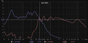
I've just been having a go a the moving mic method (MMM) for correcting driver responses etc. Here are the uncorrected curves (1/6th smoothing). My open baffle bass drivers (15" Monacor PA units) are much more efficient than the panels. The curves included the effect of LR 24 db/octave crossovers @ 400hz. My PEQ files aim for 61db. This means large cuts across the board for the OB bass. The panel response is pretty lumpy, but 61db is a reasonable compromise for a mixture of PEQ boosts & cuts.
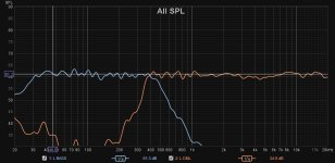
The second image shows the results of the driver corrections. You will see that around the crossover region, the bass runs too high and the DML too low. Therefore, I adjusted the crossover frequencies for both drivers.
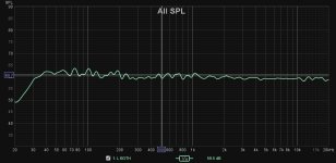
The third images shows the final response curve for the left hand speaker, taking account of the crossover fudge and some other minor corrections.
All measurements involved using the MMM with typically 80-100 measurements averaged for each reading. All images show 1/6th smoothing.
Attachments

The RTA in REW is a very nice feature indeed!
If you mess around with the smoothing in RTA Spectrum mode, and use white noise as a source, then you can get the same curve as when you do a sweep, but live! So you can move the mic around the room or 1 or 2mm away from the panel itself to see what it's doing where.
The FFT length setting will determine the resolution at low frequencies, so you'd want a higher number for better resolution. A shorter FFT length will give you more rapid readings.
There are also the Current, Peak and Both buttons (top centre of the RTA page) that will print your RTA readings directly into the graph page for later reference. Very handy! (But I don't think you can do any impulse-related analyses with them.)
Eucy,
Humor seems to be odd regionally. For example, in the southern US, when we say "well, bless your heart!", we definitely don't mean, "bless you". We really mean, "well, you can just go straight to hell, you son of a b#$%&!" And we say it with the sweetest smiles on our faces, too!
Humor seems to be odd regionally. For example, in the southern US, when we say "well, bless your heart!", we definitely don't mean, "bless you". We really mean, "well, you can just go straight to hell, you son of a b#$%&!" And we say it with the sweetest smiles on our faces, too!
I've set my FFT to 64k, RTA to 1/48th octave and no smoothing. It seems to work pretty well. I could try upping the FFT to see what happens.The RTA in REW is a very nice feature indeed!
If you mess around with the smoothing in RTA Spectrum mode, and use white noise as a source, then you can get the same curve as when you do a sweep, but live! So you can move the mic around the room or 1 or 2mm away from the panel itself to see what it's doing where.
The FFT length setting will determine the resolution at low frequencies, so you'd want a higher number for better resolution. A shorter FFT length will give you more rapid readings.
There are also the Current, Peak and Both buttons (top centre of the RTA page) that will print your RTA readings directly into the graph page for later reference. Very handy! (But I don't think you can do any impulse-related analyses with them.)
Further to post #9,068,


There could be a small additional aluminium membrane within such a small gadget, but the vibration transfer is only through single point. On the question HF, more or less the same response could be achieved with aluminium foil disk between the "normal" exciter and the panel. Only, the commercially available cheap "normal" exciters don't even go above 12kHz without load.
The AER bbx exciter is, well, 3.600 €. Oops!
If I remember, you don't have measurement equipment. Could you detail what is "in detail"?As shown in the 3 graphs above in the post #9,069 or in any other posts with audio response graphs, anything shown between 10k and 20k is just general. Does anyone have a program that shows what's happening between 10k and 20k in detail?
You have used "load" in different posts but I am not sure to understand. What means "load" in your posts?without load
Interesting test André but difficult to analyze.Here's a 40W, 32mm VC DAEX32QMB-4 MegaBass driver,(red curve) around $22-00, compared to a 20W, 25mm VC DAEX25Q-4 (blue curve) at around $14-00.
The panel was a 5mm polycarb Twinwall panel (pic attached), 540 x 550 in size. I think that's one of the dimensional golden ratios for the most even distribution of modes. The panels were un-damped, supported top and bottom only on 5mm foam tape.
I have adjusted the relative levels to make bandwidth comparisons easier.
There's a significant peak at 15k on both drivers which is not there on EPS (with Kevlar skins) nor on anything else I've tried. I suspect the peak is due to the size of the corrugations in the Twinwall. I need to test this by filling in some of the channels around the driver with silicon, or glue. Or something.
View attachment 1136983View attachment 1136982
I had a look to the exciter specifications and compare to the only one I know and use the DAEX25FHE-4.
- DAEX25Q-4 : inductance is twice the FHE (0.23mH for 0.1mH). The rest is similar
- DAEX32QMB-4 : the spec is almost empty. Inductance is not very high at 0.23mH so same as your other exciter; the cutoff frequency due to the inductance might be the same. No indication of the moving mass but a frequency of resonance much higher, 480Hz against 224Hz. Having a 32mm voice coil, we can suspect the voice coil mass to be more important than in the 25mm and the stiffness of the spider much more important; important enough to change the LF response?
You could probably evaluate the stiffness and mass of the exciter using the technique of added mass used to get the Thiele and Small parameters of a loudspeaker (technique based on the electrical impedance measurement)
When time comes, and when the two people with very good hearing are satisfied, someone else will check them with professional equipment. And, that will be free of charge. Then, it'll be not subjective. And, no self-deciet.If I remember, you don't have measurement equipment.
Look left and right of those graphs from 10k. Can your program(s) expand the area from 10k to 20k? Even if that is possible, what's the use as the "normal" exciter doesn't even reach 12kHz without load?Could you detail what is "in detail"?
Simple, a load is a load. You add the panel to the exciter...You have used "load" in different posts but I am not sure to understand. What means "load" in your posts?
Last edited:
Yes, most of us here, who actually BUILD PANELS and who UNDERSTAND THE ISSUES do use a program that shows in "what's happening between 10k and 20k in detail"Does anyone have a program that shows what's happening between 10k and 20k in detail?
What is it that you really want to know? Frequency response above 10kHz? Phase? Driver load impedance? Impedance phase? Waterfall decay times? Spectrographs?
...Distortion?
Or maybe you can tell us why distortion measurements above 10Khz are not only pretty much useless in general, but also impractical for the instruments we commonly use on this forum...
It confirms we are not following the same way. I will have a look to your posts by late spring to see your achievements.Can your program(s) expand the area from 10k to 20k? Even if that is possible, what's the use as the "normal" exciter doesn't even reach 12kHz without load?
Thanks Christian,Interesting test André but difficult to analyze.
I had a look to the exciter specifications and compare to the only one I know and use the DAEX25FHE-4.
- DAEX25Q-4 : inductance is twice the FHE (0.23mH for 0.1mH). The rest is similar
- DAEX32QMB-4 : the spec is almost empty. Inductance is not very high at 0.23mH so same as your other exciter; the cutoff frequency due to the inductance might be the same. No indication of the moving mass but a frequency of resonance much higher, 480Hz against 224Hz. Having a 32mm voice coil, we can suspect the voice coil mass to be more important than in the 25mm and the stiffness of the spider much more important; important enough to change the LF response?
Yes, I find that the specs are fairly pointless. Even when they provide inductance measurements, I find that there's no discernible pattern where I can say "oh, look, low inductance, therefore good bandwidth." There are other factors involved (BL? VC Diameter? Compliance?) that might interact with the panel factors to produce predictable performance.
It's all down to tinkering and testing and measuring I'm afraid. Of course, the fact that most of us here (of a certain age) are not able to identify anything over 10kHz is another part of a different problem.
Yes, I will certainly be employing added mass techniques to find TS parameters. It looks like BillionSound does exactly this (it looks like they are the suppliers to Dayton, Tectonic and Pui. But not to Visaton nor Monacor) They provide obvious added-mass graphs and an attempt at TS parameters on their drivers, but the text is (purposely?) too low resolution to read.You could probably evaluate the stiffness and mass of the exciter using the technique of added mass used to get the Thiele and Small parameters of a loudspeaker (technique based on the electrical impedance measurement)
- Home
- Loudspeakers
- Full Range
- A Study of DMLs as a Full Range Speaker