Eucy.
It is easy to implement on a small panel, large panels will probably be better off just using weights.
There is only one way to find out if it works, it worked for my small panel , it is just another option.
Steve.
It is easy to implement on a small panel, large panels will probably be better off just using weights.
There is only one way to find out if it works, it worked for my small panel , it is just another option.
Steve.
On the 25mm CT type 10W exciters Dayton Audio sells today, they say,Also Dayton states this note on all its exciters.
Note: An exciter's frequency response and sensitivity are completely dependent on the exciter's designated surface. Thinner, smaller materials will tend to be louder and create a mid/tweeter response. Thicker, larger materials (with multiple exciters) will be slightly quieter but result in a more full-range sound.
Do you think is it possible to make 20-20000Hz DM panels with such a weak exciter? Even with 4 exciters à la Tectonic DML500?
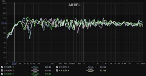
I can report that using multiple measurements when doing EQ type things is still working wonders. I've increased the number of measuring points from 3 to 5 with a spacing of about 10 inches between them. Here's the result with the mic height and position about where my ears would be.
Attachments

Lordtarquine.
Why use fixed points when you can use one measurement by moving the microphone for an average response?
Steve.
Why use fixed points when you can use one measurement by moving the microphone for an average response?
Steve.
What is your own target? requirements about bandwidth, number of ways, efficiency, dimensions..?Do you think is it possible to make 20-20000Hz DM panels with such a weak exciter? Even with 4 exciters à la Tectonic DML500?
What should be the target, do you think, with that exciter? DAEX25CT 10WWhat is your own target? requirements about bandwidth, number of ways, efficiency, dimensions..?
+ @proxiiWhy start with 2 excitors per panel?
One can produce extraordinary sounding DMLs with single exciters.
Don't complicate something before you have a reason to do so.
Start simple.
Hello Proxii
The question of the number of exciter was discussed in this thread probably several time. What I remember from the last time I joined the discussion on that :
- Several exciters is a solution to increase the power capability (see the PA DML examples)
- It is said also to get a better mechanical balance to the plate (a single exciter is usually of axis)
* the consequence on the HF extension is not clear
See post #5570
Keep in mind the possibility to shunt one of the exciter with a capacitor to get only one source in HF to avoid any cancellation.
I am from the general opinion that one exciter is the starting point (and remains for me the reference solution) in home application.
4 minutes between my question and your post... which not an answer but an other question. Good performance. What are your requirements for the system you intent to do when spring will be here is my question.What should be the target, do you think, with that exciter? DAEX25CT 10W
I'll be using a different exciter then.What are your requirements for the system you intent to do when spring will be here is my question.
But for now, you tell me what can you expect from such a weak exciter, if you'd use such an exciter on a large panel, like 4-5mm plywood panel? Or, even somewhat lighter EPS panel? Do you think, you'd reach 50-15000Hz level at least?
Actually, there's only two types worse than that 10W exciter at Dayton Audio, 3W and 5W.
Last edited:
Excuse me butting in on your conversation, but please correct me if I'm wrong...Steve - can a weighting point also be a mounting point ?? - there's no inertia involved in a mounting point...Or am I missing something?
Eucy
It seems to me that there are various types of inertial points on any DML panel, the question is merely what those inertial points' mechanical impedances are:
The first 'mounting point' could be the driver since this is what imparts the driving signal to the panel in order to set it in motion. Whether the driver is fastened to a mounting point itself or not is of no mathematical consequence. If the driver is mounted via a very stiff strut to the frame, then its Zm (mechanical impedance) will be low. If it's mounted free, fastened to the panel only by sticky pads and nothing else, then its Zm is inversely proportional to frequency (high Zm at low frequencies, and low Zm at high frequencies.) Of course one would expect the designers (Dayton? Tectonic?) to design the drivers in such a way that their lowest usable frequency (WHEN MOUNTED TO A PANEL) would be below the product of its own weight and the compliance of its own spider/surround.
Keep in mind that the driver 'mounting point' should exclude gravity IF bolted to a beam, otherwise the weight of the magnet eventually plays havoc with the position of the voice coil in the pole gap.
The second is the question of the panel frame.
IF the panel is clamped to a frame, then there could be multiple inertial points corresponding to the positions of the clamps (which do not need to be along the edges of the panel!) But the frame position could also be considered an infinite inertial point if the whole perimeter is clamped equally.
And then the compliance of the clamps needs to be considered—Do the clamps allow limited, linear movement, (Zm = x)? or are they solid, allowing no movement (Zm = 0)? or are there no clamps at all (Zm = ∞)?
The third case is those where individual weights are applied to various positions on the panel. These are also 'inertial points' of a kind, and just like the driver, their Zm also becomes inversely proportional to frequency—Such weights will be relatively inactive below a certain frequency (and will simply move along with the motion provided via the panel), and will provide only an additional mass to the panel up to a higher frequency at which the weight becomes resonant with the panel material. And it's at that physical position where the added mass acts like a Helmholtz resonator, and will suck out the offending antinode, and then provide an effective inertial (mounting) point above its resonance with Zm=0. The thing is to identify that specific part of the panel which is resonating at the offending frequency, and applying the correct mass AND compliance in order to damp it correctly. It's not just a case of gluing a washer to the panel at a supposed Eigenmode (which will provide a very high Q notch with a very sharp dip) nor is it a case of randomly adding a pieces of weather tape across the panel (a low-Q solution randomly targeting something or other, without knowing what or where the Eigenmodes actually are.)
I do apologize if this all sounds like a lecture. I'm not quite sure of my logic around the third case as I'm muddling along via intuition and common sense. If anybody can add solid backup to refute my assumptions, then I'll listen closely.
Last edited:
I'm aiming for around 120dB SPL for use in live PA front-of-house. I'm not quite sure that this would be enough sound for a decent out-doors crowd, but it's a good starting point. I'll need AT LEAST 8 x DAEXHESF 40W, high-efficiency drivers for such performance. They will be wired onto a pair of series/parallel panels.Why start with 2 excitors per panel?
One can produce extraordinary sounding DMLs with single exciters.
Don't complicate something before you have a reason to do so.
Start simple.
But even with a single HESF driver, high frequencies are a problem irrespective of the panel material, and the response starts falling off around 1khz. This is not good.
It looks like I will eventually be forced to employ a better solution to the HF problem (DSP EQ? Separate tweeters? Dedicated HF Panels? Multiple low-power, low inductance drivers?) Currently, none of these solutions seem elegant and simple, and therefore I carry on looking although the low-power drivers (20W 25mm VC) do have MUCH better bandwidth and better high-frequency capability than the high-power (40W, 32mm VC) drivers.
BTW, I've measured single drivers vs two of the same driver connected in series. The HF does not seem to change much.
Last edited:
Yes and my question is not about this specific 10W exciter but what are the overall requirements of the system you target?I'll be using a different exciter then.
Hmm...let's say to run a ~7ft tall EPS panel, width could be between 2-3ft. Or, maybe 4mm same size plywood?Yes and my question is not about this specific 10W exciter but what are the overall requirements of the system you target?
Mind you, The assumed Usable Frequency Range of the best out of them is 60-12000Hz, that too depending on the load.
Last edited:
@Andre Bellwood
My post #5570 is perhaps not so self explaining as there is no conclusion. I compared at this time a one and a two exciter configuration on the same panel.
On the first graph, it is the standard REW view with simply a 1/6 octave soomthing. No big differences
Second graph, same records but with a frequency dependent window applied in addition. Here some FR are different. This is the indication that something happened in those FR compare to the other one. What is an other question... May be a wavelet spectrogram would say more.
For now I am in the opinion there are 2 low pass filters in DML :
Christian
Hello AndréBTW, I've measured single drivers vs two of the same driver connected in series. The HF does not seem to change much.
My post #5570 is perhaps not so self explaining as there is no conclusion. I compared at this time a one and a two exciter configuration on the same panel.
On the first graph, it is the standard REW view with simply a 1/6 octave soomthing. No big differences
Second graph, same records but with a frequency dependent window applied in addition. Here some FR are different. This is the indication that something happened in those FR compare to the other one. What is an other question... May be a wavelet spectrogram would say more.
Which range of materials have you tested? I understand you are looking for "high efficiency" but do you have made test with heavier material like plywood or even acrylic?But even with a single HESF driver, high frequencies are a problem irrespective of the panel material, and the response starts falling off around 1khz. This is not good.
For now I am in the opinion there are 2 low pass filters in DML :
- The voice coil inductance combined with the voice coil resistance that reduce the driving force when the frequency increases.
- The voice coil mobile mass combined with the panel mechanical impedance at the driving point. Here the difficulty is for light membrane which have a low mechanical impedance. It is here the proposal of test with heavier material comes to see if it is a factor.
Christian
Oh, by the way, anyone can make a speaker, a detailed guide.
Only, you won't find words Distributed Mode or DML in that guide. Stay away from those terrible patents.🙂
Only, you won't find words Distributed Mode or DML in that guide. Stay away from those terrible patents.🙂
About 2m by .6 to .9m per panel is quite large in a room! are you living in a palace? Sorry for the joke, it is you choice.Hmm...let's say to run a ~7ft tall EPS panel, width could be between 2-3ft. Or, maybe 4mm same size plywood?
Mind you, The assumed Usable Frequency Range of the best out of them is 60-12000Hz, that too depending on the load.
EPS or plywood is a solution not a specification. No requirement about efficiency?
I already read you don't like the Dayton audio products. That's your choice also and opinion. From the range 60-12000Hz should we read your target is wider? With how many ways? Subwoofer assistance?
By the way a range depending on the load (=material?) is the nature of DML
And your point is?Oh, by the way, anyone can make a speaker, a detailed guide.
Only, you won't find words Distributed Mode or DML in that guide. Stay away from those terrible patents.🙂
... not Dayton?
So which proposal? which specifications? which technical solutions?
This is VERY interesting. I did not expect a shorting cap across one driver to produce an additional boost at those frequencies. This is something worth investigating.Hello André
My post #5570 is perhaps not so self explaining as there is no conclusion. I compared at this time a one and a two exciter configuration on the same panel.
On the first graph, it is the standard REW view with simply a 1/6 octave soomthing. No big differences
Second graph, same records but with a frequency dependent window applied in addition. Here some FR are different. This is the indication that something happened in those FR compare to the other one. What is an other question... May be a wavelet spectrogram would say more.
I HAVE tried multiple piezo drivers to boost the HF, and one can selectively equalize the target frequency by resonating the capacitive load of the piezo with a series inductor. A carbon film resistor in line with the inductor coil determines the Q of the peak. But that's obviously not what's happening here (I don't think!?) I will model it and investigate.
No I have not tried plywood. I have a cut-off density of around 100kg/m3. Beyond that the efficiency dies.Which range of materials have you tested? I understand you are looking for "high efficiency" but do you have made test with heavier material like plywood or even acrylic?
I have tried corrugated polycarbonate (Twinwall). It's around 70kg/m3, and it's borderline acceptable with a better bandwidth than EPS. But it's very lively and needs a lot more damping.
The other thing is that it's got different bending stiffness in 90° directions. Therefore, I should be able to(?) accommodate a high aspect ratio but with similar material wavelengths. To Be Confirmed...
Yes, exactly. Higher power drivers have higher inductances (thicker coil-wire, therefore more turns for given Re, therefore higher L.)For now I am in the opinion there are 2 low pass filters in DML :
- The voice coil inductance combined with the voice coil resistance that reduce the driving force when the frequency increases.
(Maybe I should build my own 1-ohm high-power exciters and run 4 of them in series (with shorting or resonant capacitors???))
Yes, I agree with your logic. I have suspected that a higher bandwidth does have a negative impact on efficiency. Therein lies the rub.
- The voice coil mobile mass combined with the panel mechanical impedance at the driving point. Here the difficulty is for light membrane which have a low mechanical impedance. It is here the proposal of test with heavier material comes to see if it is a factor.
What's the solution to bandwidth vs efficiency??
I have given a passing thought to testing panels with LOW Fc, rather than with high Fc. Just to see the difference.On top of that, as the roll off seems to be more 6dB/dec rather 12dB/dec (to be confirmed, expected with the 2 low pass filters combined above), a mechanism that increases the level with the frequency might be at work. It could be the increase of efficiency shown in papers when the frequency increases up to the coincidence frequency. The point is coincidence frequency and mechanical impedance are not independent. Nevertheless, some modeling might be possible.
Christian
But I do not have sufficient math to model the curves either above nor below Fc, so I'm stuck measuring it all....
Go all the way down that link. Everything is explained, without, of course, the word DML..., even the 2/5, 3/5 position is there, what else one needs?! Buy a few, and you are a speaker builder! 🙂And your point is?
... not Dayton?
So which proposal? which specifications? which technical solutions?
- Home
- Loudspeakers
- Full Range
- A Study of DMLs as a Full Range Speaker