^
There are a few more threads... but this is a good start. Depending on your choice, you might need to alter the circuit a bit.
https://www.diyaudio.com/community/threads/replacement-for-toshiba-2sk170-2sj74.317563/
There are a few more threads... but this is a good start. Depending on your choice, you might need to alter the circuit a bit.
https://www.diyaudio.com/community/threads/replacement-for-toshiba-2sk170-2sj74.317563/

I understand that J176 have been suggested as an alternative. Are the J175
and J177
close enough to consider?
| (P JFET TO92 DSG P Channel Junction FET 30V 50mA IDss=7-70mA 125R) |
| (P JFET TO92 DSG P Channel Junction FET 30V 50mA IDss=1.5-20mA 300R) |
edit, after realizing that I'm answering thinking of being in completely different thread 
you must use complementary pair of input JFets
or - you can use random paired N and P channel JFets, but then only God knows what results are going to be
even if you succeed in arranging them to bias properly
you must use complementary pair of input JFets
or - you can use random paired N and P channel JFets, but then only God knows what results are going to be
even if you succeed in arranging them to bias properly
The issue comes down to transconductance. The J113 and J176 as examples have lower transconductance
than the K170/J74 Jfet types, and so will have less capacity for processing feedback. Also the 113/175
examples have a quite different transconductance from each other. These issues can be addressed by
using different quantities of them in parallel and degenerated, but it's a pain in the butt. Easier to spend
a little money on the K170/J74's.
Hi, folks! I'm Will & I've just joined the forums here... My ACA Mini kit is my first DIY electronics project that involves soldering, so I'm a bit anxious about it, but I can power through...
However! My ACA Mini kit's power resistors don't match what's in the Guide. I need help literally on the first step. Am I supposed to use these 3W R33's or something?
However! My ACA Mini kit's power resistors don't match what's in the Guide. I need help literally on the first step. Am I supposed to use these 3W R33's or something?
Attachments
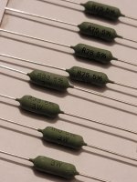
The resistors labelled "R33" are 0.33 ohms. Regard the "R" as a decimal point. "1R0" equals 1.0 ohms; "R75" is 0.75 ohms.
@willhouse Take a look at the last 2 bullets in step 7, there’s explanation there.
https://guides.diyaudio.com/Guide/ACA+Mini/21?lang=en
https://guides.diyaudio.com/Guide/ACA+Mini/21?lang=en
Will, considering your experience, use the guide written by 6L6 (Jim) linked in the post above as you put the ACA Mini together.
There seems to be a slight difference in what Will has and what the photos (in both Jim's guide and the original ACA mini article) show. Specifically, Will
has a couple of 0.33 ohm, 3 watt resistors (R33 3W) while the photos have 0.33 ohm, 5 watt (R33 5W) resistors. The 0.75 and 1 ohm resistors appear the same.
@willhouse : If you're concerned about 5W vs 3W then don't worry about it. 3 watt rating is adequate and is actually what is listed in the original article's bill of materials.
Also be very careful to not overlook the “K” in resistors which are marked or which you’re measuring with your voltmeter/ohm meter, which of course means “times a thousand”. A very common mistake…
is good practice to misure the resistor before put on pbc....match tooHi, folks! I'm Will & I've just joined the forums here... My ACA Mini kit is my first DIY electronics project that involves soldering, so I'm a bit anxious about it, but I can power through...
However! My ACA Mini kit's power resistors don't match what's in the Guide. I need help literally on the first step. Am I supposed to use these 3W R33's or something?
Hey, thanks everybody! My ACA Mini is alllllmost complete now.
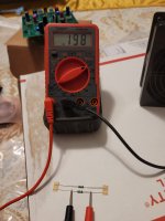
I did encounter one more issue: instead of three 6.81K resistors, my kit had just one, & then a pair of these pictured beasties. Has my measuring of all the others been faulty, or am I right in thinking that my kit's contents could have been mispicked?
I did encounter one more issue: instead of three 6.81K resistors, my kit had just one, & then a pair of these pictured beasties. Has my measuring of all the others been faulty, or am I right in thinking that my kit's contents could have been mispicked?
Attachments
Will,
There was a modified BOM in post #1355:
https://www.diyaudio.com/community/threads/diy-aca-mini.379037/page-68#post-7156140
It's quite possible (given you only have one 6.8K resistor and what looks like a couple of 200k ones) that your kit was based on this BOM.
There was a modified BOM in post #1355:
https://www.diyaudio.com/community/threads/diy-aca-mini.379037/page-68#post-7156140
It's quite possible (given you only have one 6.8K resistor and what looks like a couple of 200k ones) that your kit was based on this BOM.
I totally missed that. Neat.
Which also means the lone 6.81K is intended for R0, and all that does is set the brightness of the LED.
It reflects the changes: R2 = 200K, and R4 = 22.1K
Which also means the lone 6.81K is intended for R0, and all that does is set the brightness of the LED.
All the other resistors checked out just fine (not set to megs!) & the assembly was quite straightforward. I was able to catch the one problem, thankfully, so I just ordered up a few more 6.81K units from digikey according to the BOM's description.
Thanks again, good peoples!
I have a cool plan to build this into a small-footprint turntable system, btw, for the tiny lil' college bookstore where I work. Once that starts coming together y'all can expect a few choice pics.
Thanks again, good peoples!
I have a cool plan to build this into a small-footprint turntable system, btw, for the tiny lil' college bookstore where I work. Once that starts coming together y'all can expect a few choice pics.
- Home
- Amplifiers
- Pass Labs
- DIY ACA mini