One functional observation is that if you make the mounting holes the appropriate distance and face the MOSFETs a certain way, the holes can double as mounting holes for the PCB if you want to use the solder lug heatsinks, or you can use those holes to put the screw through the outputs and mount it to a heatsink. You may have already thought of that.
Also, where the caps rest, just my OCD but I like to put as many of those traces on the bottom. Don't make a career out of it per se but if you can easily switch them to the bottom and they don't cross any other traces, why not?
Lastly, if you can kind of scrunch the PCBs a bit looking top to bottom, they will fit on a smaller heatsink. TBH, the ACA mini produces such a small amount of heat that it may even be able to be mounted to just an aluminum chassis with maybe a 3mm thick aluminum panel. I haven't tested that of coarse.

If you're willing to change the I/O around you can probably make the whole layout more efficient. And an easy one; move the line from Q4 to P2 to the bottom layer and you can get rid of the vias in the power line that crosses it.
By "more efficient" do you mean shorter traces?
I wanted to keep the power line on the bottom layer so it's not directly under the heatsink in case the protective layer gets rubbed off. Is that even a thing to worry about?
I used Sil-Pad insulators between the TO-220 MOSFET bodies, and the heatsinks. The Keratherm 86/82 insulators sold in the Store are superb, and would be more than enough (i.e. overkill) for these TO-220 transistors with their relatively small dissipation. I'd suggest saving some money and instead using
- Bergquist part number 1009-58 (0.35 Kelvin / Watt)
- Bergquist part number SP600-90 (0.35 Kelvin / Watt)
- Bergquist part number SP400-0.007-00-51 (1.13 Kelvin / Watt)
- Any of the eBay "TO-220 Insulator Pad" packs of 100 insulators for dirt cheap (no specs stated)
Is it possible to obtain the 3D printer files (PM if preferred) I really like the look of it and my friend could print one.Wow! That 3d printed base looks gorgeous!
Thanks in advance
Eric
Whaou, thanks a lot for this new addition, Papa!
Enjoy your day (now safe from the villagers with torches)
Claude
Enjoy your day (now safe from the villagers with torches)
Claude
One functional observation is that if you make the mounting holes the appropriate distance and face the MOSFETs a certain way, the holes can double as mounting holes for the PCB if you want to use the solder lug heatsinks, or you can use those holes to put the screw through the outputs and mount it to a heatsink. You may have already thought of that.
I had not thought of that but that makes a lot of sense. Will do, thanks for the suggestion.
Also, where the caps rest, just my OCD but I like to put as many of those traces on the bottom.
May I ask the reasoning behind this? Thanks.
Lastly, if you can kind of scrunch the PCBs a bit looking top to bottom, they will fit on a smaller heatsink. TBH, the ACA mini produces such a small amount of heat that it may even be able to be mounted to just an aluminum chassis with maybe a 3mm thick aluminum panel. I haven't tested that of coarse.
I was able to shorten the vertical length by 3mm but that's about it 🤷♂️
If yer terrified of shorts due to solder mask pinholes, apply N layers of Kapton tape to PCB before stuffing and soldering. It's an excellent insulator and good up to very high temperatures.
Thanks Mark, that is a good idea. I should really have a roll of that stuff on hand anyways. I am not terrified of shorts but rather think of it as low-hanging fruit assuming the traces don't cross.
An even lower-hanging fruit is to space the components apart from the PCB (thus the soldermask) by the thickness of a popsicle stick. Apply stick, stuff component, solder leads, remove stick. Voila an air-gap 2mm wide. Air is an excellent insulator. Or, leave the popsicle stick in place. Wood is a pretty good insulator too.
Just in case "popsicle stick" is accidentally a regional idiom instead of a universal expression, here's an illustration.
_
Just in case "popsicle stick" is accidentally a regional idiom instead of a universal expression, here's an illustration.
_
Attachments

I have plenty of business cards laying around, so I generally cut them into strips and use double or triple thickness to get the shim spacing I like.
Edit: Meant to say business cards not bloody credit cards.
Edit: Meant to say business cards not bloody credit cards.
Last edited:
Popsicle House amplifier... Could be interesting. I always elevate three-watt resistors or ones that I think might get hot. I have a sliver of cardboard I've been using for the better part of the year for that purpose. Cheap and non explosive 👍An even lower-hanging fruit is to space the components apart from the PCB (thus the soldermask) by the thickness of a popsicle stick. Apply stick, stuff component, solder leads, remove stick. Voila an air-gap 2mm wide. Air is an excellent insulator. Or, leave the popsicle stick in place. Wood is a pretty good insulator too.
Just in case "popsicle stick" is accidentally a regional idiom instead of a universal expression, here's an illustration.
_
we Chickens are using pcb strips for that
plenty around, from old fabrication, in various widths ..... layer, double, triple
main trick is keeping them in one place, to avoid making new ones every other day
plenty around, from old fabrication, in various widths ..... layer, double, triple
main trick is keeping them in one place, to avoid making new ones every other day
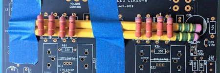
Thank you. Great tip, along with the tape, for a beginner like me.For 3 Watt resistors I recommend spacing them one-yellow-pencil-diameter above the board.
_
I was under the impression that the leads should be kept as short as possible (something about antennas?). Except for things like high wattage resistors.
Oh wow, that's pretty high. Have you had any issues that caused you to want to lift them off of the board that much?
- Home
- Amplifiers
- Pass Labs
- DIY ACA mini