I wasn’t concerned with Q1’s bias based on commentary by the creator and initially focused more on biasing Q2 to accommodate Q1: https://www.diyaudio.com/community/threads/diy-biamp-6-24-crossover.357657/post-7217662But if you replaced JFETS with 2SK170 with Idss at 8 mA, shouldn't you adapt the Q1 bias resistor to the new JFET? When I measured I got a lot higher Idss for the J113. But maybe I forgot to do the calculation with the highschool level electronics formula. 😛
Did you measure the Idss of the old J113 compared to the Idss of the new 2SK170 at the Q1 position?
I purchased 100 2sk170s from a recommended seller, measured all and grouped them based on their measurements with a 100R resistor. I found 12 that were around 8mA and used those.
When I re-measured the original Q2 current at 100R (how it arrived originally from the store), most were around ~7.5mA…a bit lower than the 12 I chose for Q1; therefore all I did was swap the original 12 Q1’s included in the kit and left everything else “stock”.
Yes, the Q1 Bias resistor is not as important, and can be set to zero or very low value. I wonder if 100 ohm is a low enough value?
I think what has confused me is measurement error when checking the J113, because in my mind they measured much higher than 10mA.
I think what has confused me is measurement error when checking the J113, because in my mind they measured much higher than 10mA.
My first measurement of the J113 with included 100ohm resistor is: 0.87V.
I = V/R = 0.87/100ohm [V/ohm] = 8.7 [mA]

I = V/R = 0.87/100ohm [V/ohm] = 8.7 [mA]
Actually more like 0.81V. I have measured a few J113 now and they all measure from 0.76 to 0.81V, according to the above method. Ready to move on to 2SK170.

No, the previous measurements were of the J113 included in the kit. The five I tested, measured from 0.76V to 0.81V.
Now to 2SK170BL:
Something strange is happening now. When testing my 2SK170BL, with the same method, but flipped pinouts on Gate and Source, I am getting voltages 0.22V and 0.20V. Fakes?


2SK170BL from another seller measures 0.24V. It is very closlely matched to 9.0 mA, according to seller. Did I get the pinouts wrong?
Now to 2SK170BL:
Something strange is happening now. When testing my 2SK170BL, with the same method, but flipped pinouts on Gate and Source, I am getting voltages 0.22V and 0.20V. Fakes?
2SK170BL from another seller measures 0.24V. It is very closlely matched to 9.0 mA, according to seller. Did I get the pinouts wrong?
Last edited:
I get the same result no matter what direction I put drain and Source on my perhaps-not-so-real 2SK170BL.
Going back to J113, the one I tested now measures 0.90V.
Going back to J113, the one I tested now measures 0.90V.
What. Pinouts double checked. Now I just got 0.23V with 100 ohm between Gate and Source on a 2SK170BL from Alweit’s own stash and matched to 8.76 mA in Alweit’s own hand writing.
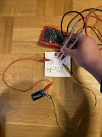
I am using a new 9 V battery in this circuit:

I am using a new 9 V battery in this circuit:
There is an ever so slight difference between the above schematic and the masters writtens words: https://www.diyaudio.com/community/threads/2sk170-matching.141162/post-1784617
Now I get 0.74V on my now-not-so-fake 2SK170 from Jakarta. Good night and a good new year.
Don’t ask me why a different schematic is needed for the J113.
Now I get 0.74V on my now-not-so-fake 2SK170 from Jakarta. Good night and a good new year.
Don’t ask me why a different schematic is needed for the J113.
Guys, if you use a 8-ish mA Idss 2sk170BL and degenerate with a 100R resistor between the gate and source, then you should get around 2-ish mA flowing through the jfet, or 0.2x volt across the 100R resistor.
If you are just trying to measure Idss then you need gate shorted to source (ie, no resistor) and you can put a resistor between the drain and V+ to facilitate the current measurement.
If you are just trying to measure Idss then you need gate shorted to source (ie, no resistor) and you can put a resistor between the drain and V+ to facilitate the current measurement.
Thanks for clearing that up.Guys, if you use a 8-ish mA Idss 2sk170BL and degenerate with a 100R resistor between the gate and source, then you should get around 2-ish mA flowing through the jfet, or 0.2x volt across the 100R resistor.
If you are just trying to measure Idss then you need gate shorted to source (ie, no resistor) and you can put a resistor between the drain and V+ to facilitate the current measurement.
The schematics I drew was not for measuring Idss, but for figuring out the bias resistor needed to adjust the current through the j113.
In order to get the Idss, NP writes in the link above that the 100ohm resistor is to be placed between ground and Gate shorted to Source. Ground is V- on my 9V battery.The schematics I drew was not for measuring Idss, but for figuring out the bias resistor needed to adjust the current through the j113.
Now you suggest to put the same resistor between Drain and V+, to in order to measure the same thing - Idss.
Could it be that NP’s suggestion works on 2SK170BL and your suggestion works on J113?
One final comment: If your j113 Q2 and its bias resistor gives about 8mA currrent and you have 2sk170 Q1 jfets with Idss in the 8mA range then I would just run them without Q1 bias resistors.

They are equivalent. The Idss current (gate shorted to source) will cause the same voltage drop acrosss this 'current sensing' resistor whether you place it between the drain and V+ or source and V-Which is the correct method?
@elwood625 I would like to get in touch with you regarding the H2 generator. I bought the board and all the components and would like to build this generator. I saw that you posted a review on the store saying you built this board with "unity gain." I am new to this whole DIY concept and never built a board before. Can you help explain what that is and how you did it? Also I noticed that your board had not input and no power supply. I would like to gt in touch and get some help from you if you are willing. Thanks.
@Dennis Hui, I left the Q1 100R bias resistor in place from my initial build. Everything seems to be working…sounds good; however, I’m concerned it’s not optimal based on your comment. Should I removed the Q1 100R resistors and replace with a jumper?One final comment: If your j113 Q2 and its bias resistor gives about 8mA currrent and you have 2sk170 Q1 jfets with Idss in the 8mA range then I would just run them without Q1 bias resistors.
ZM thought some resistance is important to have. Nelson says jumper is fine.@Dennis Hui, I left the Q1 100R bias resistor in place from my initial build. Everything seems to be working…sounds good; however, I’m concerned it’s not optimal based on your comment. Should I removed the Q1 100R resistors and replace with a jumper?
Last edited:
gate stoppers are important and must have; more critical as one is using JFet with more xconductance
everything else - what construction and parts on hand dictates and allows
personally - I don't care for series output ( protection) resistors
everything else - what construction and parts on hand dictates and allows
personally - I don't care for series output ( protection) resistors
- Home
- Amplifiers
- Pass Labs
- DIY biamp 6-24 crossover