Okay. I will try going higher and just watch the temp of the resistors etc.
I had these fairly large, at least for an ACA mini, heat sinks laying around. They are approximately 4 in by 7 in deep and from the tip of the fins to the base is about 3 in.
I'm using a glassware 24 volt dual mono power supply with a 50 VA transformer. Everything is staying very cool so far.
Later on I will be building a standard ACA mini with the essentials kit and the completion kit from the store for my daughter's room. That'll be a little project to do with her. She is 5 🙂

Okay. I will try going higher and just watch the temp of the resistors etc.
I had these fairly large, at least for an ACA mini, heat sinks laying around. They are approximately 4 in by 7 in deep and from the tip of the fins to the base is about 3 in.
I'm using a glassware 24 volt dual mono power supply with a 50 VA transformer. Everything is staying very cool so far.
Later on I will be building a standard ACA mini with the essentials kit and the completion kit from the store for my daughter's room. That'll be a little project to do with her. She is 5 🙂
Never too early to get someone into the audio hobby.😀
I agree 🙂
I just started listening to this a few minutes ago now biased at .400v and it sounds really good. It is a detailed little thing.
I just started listening to this a few minutes ago now biased at .400v and it sounds really good. It is a detailed little thing.
I found the bias is very temp dependent. It will keep going up until the heatsink temp is stabilized. I have a summer and winter settings. I would set high bias slowly and keep on checking it until you're sure things become stable.I agree 🙂
I just started listening to this a few minutes ago now biased at .400v and it sounds really good. It is a detailed little thing.
The price to pay for an ultra simple good sounding design.
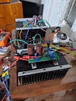
This picture might clear things up as to why they don't get hot. Lol. Those heat sinks are 3 in deep. They were just sitting in a drawer which is why I decided to use them for this project. Also, this might make for a good summer amp in a room that is not cooled very well... Or maybe my shop? Also, these are audioSteve's boards
Right now I have the at 0.470 volts. The MOSFET itself is just warm to the touch. Also it's probably about 62F to 68F in my house. Maybe I should throw a towel over the whole thing to get to warm up. Lol
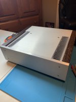
I plan to build out the rest of the case over the next couple of weeks. But so far, I'm impressed with the sound. Very detailed while making poor and good quality recordings sound very good. Sometimes detail can be the death to a good experience with an amplifier.
It is not super dynamic for an amplifier. However, It is very dynamic for a 5ish what amplifier. I'm running it on some 89 decibel sensitive speakers and it has its little grip on them just fine 🙂
High frequency sounds are very nice and clear. That's probably why I like most at this point about the amp.
I have 10 each of the positive and negative FQP devices. Maybe I can get a match out of them. I'll have to take a look. That would be fun for next project. Also I can set these hard to get Harris parts aside and not fry them by playing with bias adjustments.
I like to jumper out so far.
Question: for anyone who has matched the FQP devices for this amp, what are the parameters that they were tested at? Typically, I have seen the testing rig where it is tested at 10 milliamps. However these are being used as actual outputs for the speakers. Maybe I should test a little hotter and record the results after a duration of time? Kind of like you do with IRFP240s etc?
Right now I have the at 0.470 volts. The MOSFET itself is just warm to the touch. Also it's probably about 62F to 68F in my house. Maybe I should throw a towel over the whole thing to get to warm up. Lol
I plan to build out the rest of the case over the next couple of weeks. But so far, I'm impressed with the sound. Very detailed while making poor and good quality recordings sound very good. Sometimes detail can be the death to a good experience with an amplifier.
It is not super dynamic for an amplifier. However, It is very dynamic for a 5ish what amplifier. I'm running it on some 89 decibel sensitive speakers and it has its little grip on them just fine 🙂
High frequency sounds are very nice and clear. That's probably why I like most at this point about the amp.
I have 10 each of the positive and negative FQP devices. Maybe I can get a match out of them. I'll have to take a look. That would be fun for next project. Also I can set these hard to get Harris parts aside and not fry them by playing with bias adjustments.
I like to jumper out so far.
Question: for anyone who has matched the FQP devices for this amp, what are the parameters that they were tested at? Typically, I have seen the testing rig where it is tested at 10 milliamps. However these are being used as actual outputs for the speakers. Maybe I should test a little hotter and record the results after a duration of time? Kind of like you do with IRFP240s etc?
Attachments
I see, very niceThis picture might clear things up as to why they don't get hot. Lol. Those heat sinks are 3 in deep. They were just sitting in a drawer which is why I decided to use them for this project. Also, this might make for a good summer amp in a room that is not cooled very well... Or maybe my shop? Also, these are audioSteve's boards
as you have 35v caps....you can add some b+This picture might clear things up as to why they don't get hot. Lol. Those heat sinks are 3 in deep. They were just sitting in a drawer which is why I decided to use them for this project. Also, this might make for a good summer amp in a room that is not cooled very well... Or maybe my shop? Also, these are audioSteve's boards
Right now I have the at 0.470 volts. The MOSFET itself is just warm to the touch. Also it's probably about 62F to 68F in my house. Maybe I should throw a towel over the whole thing to get to warm up. Lol
I plan to build out the rest of the case over the next couple of weeks. But so far, I'm impressed with the sound. Very detailed while making poor and good quality recordings sound very good. Sometimes detail can be the death to a good experience with an amplifier.
It is not super dynamic for an amplifier. However, It is very dynamic for a 5ish what amplifier. I'm running it on some 89 decibel sensitive speakers and it has its little grip on them just fine 🙂
High frequency sounds are very nice and clear. That's probably why I like most at this point about the amp.
I have 10 each of the positive and negative FQP devices. Maybe I can get a match out of them. I'll have to take a look. That would be fun for next project. Also I can set these hard to get Harris parts aside and not fry them by playing with bias adjustments.
I like to jumper out so far.
Question: for anyone who has matched the FQP devices for this amp, what are the parameters that they were tested at? Typically, I have seen the testing rig where it is tested at 10 milliamps. However these are being used as actual outputs for the speakers. Maybe I should test a little hotter and record the results after a duration of time? Kind of like you do with IRFP240s etc?
Must be quite difficult to adjust the trimmer pot's with the screws on the side!This picture might clear things up as to why they don't get hot. Lol. Those heat sinks are 3 in deep. They were just sitting in a drawer which is why I decided to use them for this project. Also, this might make for a good summer amp in a room that is not cooled very well... Or maybe my shop? Also, these are audioSteve's boards
Right now I have the at 0.470 volts. The MOSFET itself is just warm to the touch. Also it's probably about 62F to 68F in my house. Maybe I should throw a towel over the whole thing to get to warm up. Lol
I plan to build out the rest of the case over the next couple of weeks. But so far, I'm impressed with the sound. Very detailed while making poor and good quality recordings sound very good. Sometimes detail can be the death to a good experience with an amplifier.
It is not super dynamic for an amplifier. However, It is very dynamic for a 5ish what amplifier. I'm running it on some 89 decibel sensitive speakers and it has its little grip on them just fine 🙂
High frequency sounds are very nice and clear. That's probably why I like most at this point about the amp.
I have 10 each of the positive and negative FQP devices. Maybe I can get a match out of them. I'll have to take a look. That would be fun for next project. Also I can set these hard to get Harris parts aside and not fry them by playing with bias adjustments.
I like to jumper out so far.
Question: for anyone who has matched the FQP devices for this amp, what are the parameters that they were tested at? Typically, I have seen the testing rig where it is tested at 10 milliamps. However these are being used as actual outputs for the speakers. Maybe I should test a little hotter and record the results after a duration of time? Kind of like you do with IRFP240s etc?
Nicoch58, good observation. Yes, they are 35v caps. I may try a higher voltage at some point. Maybe I can mock something up.
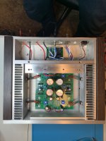
Franz, That is true. Adjusting the trimmer pots with everything as it sits is not optimal. When the heatsinks are assembled into a chassis in the side heatsink configuration, I can have a small hole drilled into the back plate of the chassis so that I can stick a long flathead in and reach the pots. The pots are oriented so that when everything is assembled, they will both face toward the back of the chassis.
Franz, That is true. Adjusting the trimmer pots with everything as it sits is not optimal. When the heatsinks are assembled into a chassis in the side heatsink configuration, I can have a small hole drilled into the back plate of the chassis so that I can stick a long flathead in and reach the pots. The pots are oriented so that when everything is assembled, they will both face toward the back of the chassis.
Last edited:
for the size of pcb if mine, I will put pcb at 90° vs heatsink to put mosfet at 2/3 ant trimmer looking at top ,the classic config lot better then backFranz, That is true. Adjusting the trimmer pots with everything as it sits is not optimal. When the heatsinks are assembled into a chassis in the side heatsink configuration, I can have a small hole drilled into the back plate of the chassis so that I can stick a long flathead in and reach the pots. The pots are oriented so that when everything is assembled, they will both face toward the back of the chassis.
A couple of reasons that I did not go that route. One, there will be a power supply in the middle so I cannot have the boards sticking out there. 2nd, the dissipation of these heatsinks are so much that the harris outputs don't even get more than around 10c above ambient in my room sitting how they are ontop of the wood. It's almost an advantage to handicap the cooling... lol Typically, I would pay more mind to the 2/3 rule of thumb.
as custom mine will not have wide/size problem ,btw will be dual monoA couple of reasons that I did not go that route. One, there will be a power supply in the middle so I cannot have the boards sticking out there. 2nd, the dissipation of these heatsinks are so much that the harris outputs don't even get more than around 10c above ambient in my room sitting how they are ontop of the wood. It's almost an advantage to handicap the cooling... lol Typically, I would pay more mind to the 2/3 rule of thumb.
Very nice. Mine is dual mono outside of the transformer. One secondary to each channel though so pretty much dual mono. The power supply that I have is a dual power supply on a single board.
I am in the process of building an ACA Mini and have pulled a couple of SK170s (BL) from an old project and wanted to know if the measurements I have show that they are ok to use. Both of them measure similarly.
I attach a pic
I attach a pic
Thanks very much. So that I might learn a little of the workings of these fets are you able to decipher the readings? I have heard the term IDSS but not sure if that applies here. Do the measurements show voltage between two or more of the pins G D S?good to go
Idss is the current that flows through the Jfet when Gate and Source are at the same voltage (tied together works)
and some voltage is applied to the Drain. I test mine at 12 volts.
The Idss of the matched ACA mini Jfets is about 5.5 to 7 mA.
and some voltage is applied to the Drain. I test mine at 12 volts.
The Idss of the matched ACA mini Jfets is about 5.5 to 7 mA.
- Home
- Amplifiers
- Pass Labs
- DIY ACA mini