
Oh, you just made my day! Thank you!
If there are questions, please feel free to ask. I tried to cover the key things but not everything.
If there are questions, please feel free to ask. I tried to cover the key things but not everything.
Could-it be possible to use values of Rsch and Rg, with Rg directly connected to GND without rv102, having an acceptable gain and keeping the triode curves?
This could omit C102 from the signal path....
This could omit C102 from the signal path....
The MOSFET Vgs has to be around 4-5V and with the bottom FETs source at about 20-25V, you want about 25-30V on the gate of the gain FET for the Vgs to work out. With the drain at 60-65V, that means a ratio of about 2:1, but Rsch and Rg need to be more like 10:1. Maybe at lower gain settings it would work out. With the pot and cap, there is a lot of flexibility and accounts for part variability also.
George suggested an alternate approach where Rsch and Rg are fixed and set for DC bias and then there is a cap in series with a pot, both in parallel to Rg. The cap and pot set the AC feedback. But again the cap is there, though it it less like a bypass cap and more like a DC blocking cap. I never explored that option.
George suggested an alternate approach where Rsch and Rg are fixed and set for DC bias and then there is a cap in series with a pot, both in parallel to Rg. The cap and pot set the AC feedback. But again the cap is there, though it it less like a bypass cap and more like a DC blocking cap. I never explored that option.
There might be one thing not discussed in detail in the manual.
The input capacitors and how large they really need to be.
ra7 has said that 10 uF is not needed and since the cap is working into 1 M Ohms one could use a much smaller and, potentially, superior capacitor here.
At 1 uF rolloff begins around 0.1 Hz. 0.47 uF is at .33 Hz.
So if time permits in this too busy time of the year I would like to know if there are other concerns about the size of capacitor that it simply seeing a 1 meg load?
Sorry to belabor the point.
Thanks
Don't forget the gate capacitance of the lower mosfet... I would say 47K as an average impedance to calculate the input cap
The lower mosfet operates as a follower so the typical "input (gate to source) capacitance" is bootstrapped, thus appearing to be much smaller than the value on the data sheet. The "output (drain to source) capacitance" is driven by the mosfet and thus buffered from the input terminal. The "reverse transfer capacitance" however is directly from the amp's input to ground and the most important spec to look at when choosing a mosfet.Don't forget the gate capacitance of the lower mosfet... I would say 47K as an average impedance to calculate the input cap
I have been building this circuit with vacuum tubes for couple years now. A couple other builders and I have seen blown mosfets that seem to be unexplainable. These have all been tiny TO-92 mosfets without gate protection zeners, and the death seems to occur when massing with input cables, especially on a live board without a volume pot. The 1 MEG to the bias pot on the gate does not always protect the gate from a static zap or an AC leakage potential difference between amps and preamps with a floating ground on one or more components. This may not be an issue with the large fets used here.
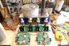
Thought I would show this picture of the TOROIDY SUPREME transformer.
Polished stainless steel cover. One wonders if this cover should be isolated from a metal chassis plate? I am going to place this one on a 0.25" balsa spacer since I do not want to run the wires to the other side of the plate.
One channel power supply using parts laying about for years. Looks like overkill but ends up being a better way to store old components.
Each power supply will be for the two channels on the SCG board - one for high frequencies and the other for low. The small HAMMOND chokes split the output to the two channels on the board.
Attachments
![IMG_0358[1].JPG](/community/data/attachments/1029/1029022-6b4d8a4e4e3319493e384cda8d28c401.jpg?hash=a02KTk4zGU)
Yes, you can go with a smaller cap there. Even 0.47 uF should be plenty enough working into 1 Meg. The gate of the MOSFET is practically an open circuit at audio frequencies. Here's a sim with 1 uF and 1Meg. Okay, the input MOSFET isn't the same, but it should work.There might be one thing not discussed in detail in the manual.
The input capacitors and how large they really need to be.
ra7 has said that 10 uF is not needed and since the cap is working into 1 M Ohms one could use a much smaller and, potentially, superior capacitor here.
At 1 uF rolloff begins around 0.1 Hz. 0.47 uF is at .33 Hz.
So if time permits in this too busy time of the year I would like to know if there are other concerns about the size of capacitor that it simply seeing a 1 meg load?
Sorry to belabor the point.
Thanks
George, I haven't lost any FETs to live cable swapping yet, even the TO-92 ones, and I have been torturing the circuit quite a bit. Right now, I have two SCGs in series working into unity gain (or even negative gain) VFET amps. And live swapping cables on the input of the first one does make nasty sounds. But not lost an FET yet. The Vgs of FETs are limited to about 20V and Nelson often puts a zener from gate to source to protect the gate. That might help. Not really needed at the preamp level, but if it is seeing large instantaneous swings in the tube circuit, maybe a protective zener would be useful.The lower mosfet operates as a follower so the typical "input (gate to source) capacitance" is bootstrapped, thus appearing to be much smaller than the value on the data sheet. The "output (drain to source) capacitance" is driven by the mosfet and thus buffered from the input terminal. The "reverse transfer capacitance" however is directly from the amp's input to ground and the most important spec to look at when choosing a mosfet.
I have been building this circuit with vacuum tubes for couple years now. A couple other builders and I have seen blown mosfets that seem to be unexplainable. These have all been tiny TO-92 mosfets without gate protection zeners, and the death seems to occur when massing with input cables, especially on a live board without a volume pot. The 1 MEG to the bias pot on the gate does not always protect the gate from a static zap or an AC leakage potential difference between amps and preamps with a floating ground on one or more components. This may not be an issue with the large fets used here.
Thanks, ra7.
Whatever I install on the board I want to remain happy with which is why I am going on and on about this.
Take care,
Whatever I install on the board I want to remain happy with which is why I am going on and on about this.
Take care,
We have been using the little VP0106N3 from Microchip as the input fet with a high Gm pentode vacuum tube for the gain device and an IXYS IXTP10M45 for the CCS. This is used as the input stage in a two stage amp. We run about 20 volts across the input fet. All work good together until they don't. Autopsy reveals a dead input fet. One user popped several but nobody else had seen dead fets until one died in my amp. I had been testing with a electrically floating phone or iPad for a source and the fet failure occurred when I live swapped in a CD player that was plugged into the line voltage. Since all of my sources are low impedance solid state devices, I wired a 22 K resistor across the input and have not blown any more fets.George, I haven't lost any FETs to live cable swapping yet, even the TO-92 ones, and I have been torturing the circuit quite a bit. Right now, I have two SCGs in series working into unity gain (or even negative gain) VFET amps. And live swapping cables on the input of the first one does make nasty sounds. But not lost an FET yet. The Vgs of FETs are limited to about 20V and Nelson often puts a zener from gate to source to protect the gate. That might help. Not really needed at the preamp level, but if it is seeing large instantaneous swings in the tube circuit, maybe a protective zener would be useful.
The output stage uses a big FQP9P25 or FQPF9P25 with a 15 volt zener from gate to source driving a large TV sweep tube on 650 volts and they don't blow. A push pull pair have been driven to 250 watts and a parallel push pull setup with 4 tubes recently made 525 watts. Now that most of that testing has been done, I should have time to play with some big mosfets and one of these SCG boards, probably after the first of the year.
This board is only the output stage. The FQP9P25 input fets are on the black heat sinks and they dissipate about 5 watts each at idle. The square boards are conventional driver and phase inverter stages, both are fully differential LTP's with vacuum triodes. Only one board is being used to drive two output boards. I ran the amp on three bench power supplies, and turned the drive up until I saw the onset of clipping at about 525 watts and 4 to 5% THD. Before I could capture all the pictures the 15 amp bench breaker tripped and the fun ended. The vertical brown thing is an 8 ohm 500 watt resistor used as a test load. It was smoking hot!
Attachments
22k seems rather high but glad to hear it solved the problem.
525W from four tubes? whaaat?
And so, both the pre and power tubes have the UNSET topology?
525W from four tubes? whaaat?
And so, both the pre and power tubes have the UNSET topology?
Hi RahulYes, you can go with a smaller cap there. Even 0.47 uF should be plenty enough working into 1 Meg. The gate of the MOSFET is practically an open circuit at audio frequencies. Here's a sim with 1 uF and 1Meg. Okay, the input MOSFET isn't the same, but it should work.
View attachment 1121132
View attachment 1121133
Thanks for the simulation.
Should I understand that the following caps: C101, C103, C201, C203 can all be replaced by a quality 1uF cap ?
Also, you’ve added a 47k before the input cap, should we be adding this? I haven’t checked if it’s already on your PCB.
Thanks
Eric
I already had several bags of resistors open on my workbench. 22K was the first one that looked low enough to keep a constant state of charge on the input coupling cap, but high enough to avoid loading if I decided to drive the board with an unknown (possible vacuum tube) source.22k seems rather high but glad to hear it solved the problem.
525W from four tubes? whaaat?
And so, both the pre and power tubes have the UNSET topology?
Yes, 525 watts came from 4 26HU5 vacuum tubes operating a bit beyond the published specs when pushed hard. This particular amp is a three stage balanced design using a Long Tailed Pair with conventionally wired triodes driving another similar Long Tailed pair. The UNSET design cannot easily be used as an LTP. The original UNSET two stage board barely has enough gain to drive a large tube to 25 watts or so in SE from a phone or iPad. I needed three stages for a BIG amp, and a 1KW (500WPC) vacuum tube amp is my end goal. This board can be driven from a single ended source but provides a balanced output for push pull output stages and has more than enough gain to apply some negative feedback if needed. Remember, electron tubes are only "N channel" devices, there are no positron tubes, so a lot of tricks used in the solid state world do not apply.
The output stage is an UNSET design very similar to what's on your board, except the CCS stage is replaced with an output transformer. The same thing can be done on your board by replacing the CCS stage with a choke.
Bob Carver made a living exploiting the fact that the peak to average ratio in even today's over compressed music is at least 10 dB, usually considerably more. This means that when your amp is cranked to the edge of clipping (525 watts in this case) its AVERAGE power output is 52 watts or less, far less on well recorded music. From the early 80's through the mid 90's my stereo system consisted of a Phase Linear 4000 driving a Carver "cube" M-400. Despite the warnings in the manual, I routinely played my guitar through that thing at full tilt, and it was still alive and well when I gave the entire system to a friend in the mid 2000's. It did get pretty hot sometimes, but it would just shut down and blink the LED's at me until I turned it down.
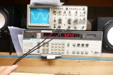
This means that you can often get away with 50 watts worth of heat sinking in a class AB amp depending on the idle current. The Carver had only the metal chassis for heat sinking and made about 300 WPC into 4 ohms. Running the tube amp to about 350 watts with a sine wave for about 5 minutes will produce a dull red glow in the plates of the output tubes. The glow diminishes when the power level passes 500 watts as the overall efficiency gets better. I stopped at 525 watts long enough to get a picture of 524.9 watts on the HP8903A, but the breaker popped before I could get a picture of the THD reading. It was 4.something, 7 I think.
In an earlier experiment I did take the first two stage UNSET prototype board where both stages are UNSET based and drove the two channels out of phase with a transformer. I got over 250 watts from one pair of slightly bigger tubes.
That experiment began in post #55 here:
https://www.diyaudio.com/community/threads/unset-is-coming.340856/page-3
That entire thread is about some of the early development of the UNSET design that actually started back in about 2016 and got shelved several times when I hit a road block. The idea was to get triode like curves from a pentode tube and eliminate the need for a negative bias supply at the same time. The seed was planted by a discussion years ago about cheap guitar amps, hence the little 50C5 board that makes 20 watts.
That 47K resistor is not on the pcb.Hi Rahul
Thanks for the simulation.
Should I understand that the following caps: C101, C103, C201, C203 can all be replaced by a quality 1uF cap ?
Also, you’ve added a 47k before the input cap, should we be adding this? I haven’t checked if it’s already on your PCB.
Thanks
Eric
I know very little about sim programs but there is lots about that drawing that is different from the pcb circuit.
I decided to use 0.82 uF for the high frequency channel and 1.5 uF for the low frequency channel which cuts off at 80 hz.
TUBELAB is simply a wonder. The Jeeves of audio. I am lucky to even reach Wooster status ...
Yes, that is an old sim that works for illustrating the impact of the input cap on the frequency response. Do not use it for the PCB. The first post links to the latest schematic.Hi Rahul
Thanks for the simulation.
Should I understand that the following caps: C101, C103, C201, C203 can all be replaced by a quality 1uF cap ?
Also, you’ve added a 47k before the input cap, should we be adding this? I haven’t checked if it’s already on your PCB.
Thanks
Eric
I am building second SCG pre and about to order these power transformers. They worked great for me first time. If anyone is interested.
https://www.tubesandmore.com/search/node/P-TN-68X
https://www.tubesandmore.com/search/node/P-TN-68X
I use one transformer per channel. Only 115 secondary. Its a small transformer and gets a little warm. But not hot. Can be used in europe too 🙂
Btw, i replaced one 15v zener diode in one channel, and now it biases nicely, both channels. I had 100volts on correct channel, but only about 87volts in other. One bad zener. All good now, already for few days in the main system. Sounds fabuloso. Already dethroned korg nutube pre.
Btw, i replaced one 15v zener diode in one channel, and now it biases nicely, both channels. I had 100volts on correct channel, but only about 87volts in other. One bad zener. All good now, already for few days in the main system. Sounds fabuloso. Already dethroned korg nutube pre.
- Home
- Amplifiers
- Pass Labs
- Schade Common Gate (SCG) Preamp