
Yes, what , the essence is about a correct summation of the port output with the driver output in case of bass-reflex system. The port cross-section is important to take into account for a correct output level.

It only applies to bass-reflex cases. In the document a significant number of different systems were tested, and all gave a correct summation.
Bass-reflex is not my cup of tea, but the difference with the "old" formula at the resonance frequency was 2.5 dB or so.
Which is quite some difference if it were sealed box, so i assume also for bass-reflex.
Last edited:
Just do not use wax to hold the feathers 😎🤣Sure it could be improved, but it’s sound advice.
He who would learn to fly one day must first learn to stand and walk and run and climb and dance; one cannot fly into flying.
Nietzsche
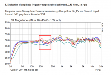
Thanks for the PDF. Btw The speaker in the PDF shows good example that it is possible to make quite bad port for a bass reflex system. Here the port resonance is ~7db louder than Helmholtz resonance and in order to tame it with loads of damping away goes the Helmholtz resonance and associated bass boost. The other resonance, from the port or leaking from the box around 600Hz is also very loud even with the damping in place.I found an interesting comparison between different types of measurements of the same speaker (nearfield+farfield merged, ground plane vs Klippel NFS) done by different individuals and published by FM stoneeh over at ASR. Please find the attached document for the same. I, for one, really appreciate his efforts.. 🙂
From what I understood from the attached document, what was more interesting to me is that FM stoneeh mentions about some improved formula for nearfield+farfield merging, and he has an article about it here:
Now I really wish I knew some German language at least enough to understand what the new method in the above video is.. 😀

How did they succed to make it so bad? Worst case I've ever seen, but it was a simple undamped test box. Examples in the beginning were "normal".
Last edited:
Small two way boxes are prone for this kind of problems as the pass band is wide and box small and port long. Prototyping is highly recommended so that bad port inlet position can be changed for better. I would guess the PDF author has already built another box with another solution.
The PDF frequency response plot shows nice action for the tuning, nice low frequency extension, but I suppose it is before damping the vent as there is ~3db anomaly where there resonance is. I suspect the coloration from this kind of resonance is very audible and worth it to weed out, by building another box.
The PDF frequency response plot shows nice action for the tuning, nice low frequency extension, but I suppose it is before damping the vent as there is ~3db anomaly where there resonance is. I suspect the coloration from this kind of resonance is very audible and worth it to weed out, by building another box.
Attachments
Till i get the abrorber panels, here is a video of the speakers playing some music from YouTube .. Just for fun.. 😀
I think the echoes caused by the room can be heard in this one 😀
But even with all that around 1.50 min in the video, it is really fun to hear.. 🙂
I think the echoes caused by the room can be heard in this one 😀
But even with all that around 1.50 min in the video, it is really fun to hear.. 🙂
Last edited:
Still waiting for acoustic panels.. In the meanwhile trying out this version of crossover (with linear phase crossover blocks). 🙂
Crossover

System Response


I notice a tiny bit of wiggles in the step response above around 0.5ms? Is it Pre-ringing artifact?
And if at all they are audible, do they have some specific sound signature?
Crossover
System Response
I notice a tiny bit of wiggles in the step response above around 0.5ms? Is it Pre-ringing artifact?
And if at all they are audible, do they have some specific sound signature?
Anything but a flat line before the peak is pre-ringing or time mismatch between playback and recording clocks.I notice a tiny bit of wiggles in the step response above around 0.5ms? Is it Pre-ringing artifact?
And if at all they are audible, do they have some specific sound signature?
You can have this anyway if your DAC uses a linear phase anti aliasing filter. The pre-ringing of linear phase crossovers can be completely cancelled if they are completely complementary acoustically.
https://www.diyaudio.com/community/threads/pre-ringing-who-has-heard-it.329993/
An example of audible pre-ringing here but you have to work pretty hard to get something as bad as this, the "woop" before the snare hit.
Question, how do you figure out if it is preringing or a clock mismatch?
Remove any linear phase EQ or crossover filters and see the difference. If the A/D and DAC are run from the same master clock there should be no drift but if a USB microphone is used that can't happen.
Otherwise window the measurement to show only the response before the peak and look at the frequency response or filter the IR to see what shows up.
Clock drift is usually seen as a slow ramp up.
REW has a clock drift compensation feature.
Otherwise window the measurement to show only the response before the peak and look at the frequency response or filter the IR to see what shows up.
Clock drift is usually seen as a slow ramp up.
REW has a clock drift compensation feature.
Do you mean this:


Measurements doen with Arta in combination with old m-audio ext interface
Measurements doen with Arta in combination with old m-audio ext interface
Last edited:
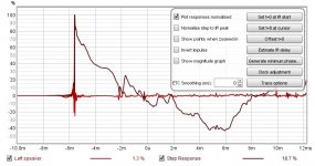
Yes, although it's easier to see without the ETC overlaid, in percentage instead of dBfs and zoomed in to see the window better.Do you mean this:
Last edited:
Thanks @fluid 🙂
I am going through the above thread you linked.
I made small adjustments to the above crossover and took measurements 1m away from the speaker.
This is how the impulse and step response looked like for one of them (Left speaker).

Below is about 3.4ms gated response of the left and right speakers

At the moment, I cannot make out the differences between the earlier minimum phase crossover-based system I had and the above linear phase crossover version.
But anyway I am enjoying the speakers a lot. 😀
They sound relaxed with some nice bass. Once I have the acoustic panels, I will redo listening position measurements and try and study all changes they bring in.. 🙂
I am going through the above thread you linked.
I made small adjustments to the above crossover and took measurements 1m away from the speaker.
This is how the impulse and step response looked like for one of them (Left speaker).
Below is about 3.4ms gated response of the left and right speakers
At the moment, I cannot make out the differences between the earlier minimum phase crossover-based system I had and the above linear phase crossover version.
But anyway I am enjoying the speakers a lot. 😀
They sound relaxed with some nice bass. Once I have the acoustic panels, I will redo listening position measurements and try and study all changes they bring in.. 🙂
Attachments
That does not surprise me, your minimum phase version didn't have any real significant time problems. If you used LR4 or higher for the lower crossover frequency then I think you would, with an LR2 you would need the right source material and have trained yourself a bit to stand a chance of hearing it.At the moment, I cannot make out the differences between the earlier minimum phase crossover-based system I had and the above linear phase crossover version.
Think twice about training yourself to hear problems that you don't now 🙂
So, the first 2 acoustic panels are ready. 😀 (From preliminary sweeps/songs played, I dont think these panels are doing anything much w.r.t where they are placed currently because of the monster of room I have audio quality-wise)

Each is 6ft x 2ft, 200mm thick. They have wheels and are easy to move around.
So where should they be placed ideally? (at first reflection points or at the back of speakers or at the back of my sofa where I sit). And what am I aiming for w.r.t measurements..? Is it a better decay time/wavelet spectrogram?
In the meanwhile, some other drivers have arrived (This is the last compression driver that I will buy 😀)

Regards
Vineeth
Each is 6ft x 2ft, 200mm thick. They have wheels and are easy to move around.
So where should they be placed ideally? (at first reflection points or at the back of speakers or at the back of my sofa where I sit). And what am I aiming for w.r.t measurements..? Is it a better decay time/wavelet spectrogram?
In the meanwhile, some other drivers have arrived (This is the last compression driver that I will buy 😀)
Regards
Vineeth
Dear Vineeth,
I would like to suggest that you don't try to clear the room using panels, as no amount of the same would ever suffice. Instead, just build a full-size baffle wall for the speakers (and also get a bass bonus of ~3-4dB) as the room seen in the photograph appears to be rather empty. You may treat the wall behind the baffle using the regular ugly thermal insulation materials that are cheaper when bought in bulk. The aesthetically superior panels may then be used within the visible areas of the room to control the side/back wall reflections etc.
Absorption being lossy is never completely achieved, but the baffle wall would neatly "turn" the back-wave towards the listener (and improve efficiency) down to the lowest frequencies that panels cannot handle. When you can't kill it, turn it !!
All the best.
I would try lateral first reflection points, across the room corners and behind the listening position if there is wall close behind.
Take some measurements and look at the ETC and early decay plots to see the effect.
Take some measurements and look at the ETC and early decay plots to see the effect.
I will try out more measurements with panels tomorrow and post it here.. 🙂
In the meanwhile, here is a video of a video from youtube playing through the speakers.. 😀
After listening for some time, I feel that panels are having some effect, however little it is.. It is something like the music has calmed down little bit and speakers have a bit better imaging. Let me see if i can see these in measurements somehow.. 😀
Last edited:
Me, myself and I don't have any experience with acoustic treatment. so, following your experiments will be very educative!
My common sense says that the area of your panels is small relative to total wall area. Having wheels makes if very easy to search for best effect. I guess you should try placing them beside the sofa where you sit when listening, and not along the back wall but at 90deg. That way they could kill reflections near your ears, maximizing the effect?
Nearfield of ears makes max effect- You can test this by using your hands as horns!
- Home
- Loudspeakers
- Multi-Way
- A 3 way design study