I haven't got further from simulations for now. Unfortunately my time is needed elsewhere. Here's the crossover sim for frequency response from ATH thread - it should present a good starting point.
View attachment 1109467
Interesting, thanks!
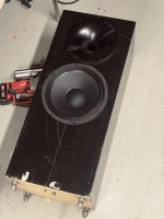
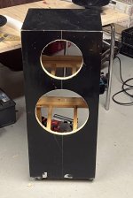
Before starting to route holes for ST260/B and 12PR320:
ST260/B diameter: 259mm /2 = radius 129,5mm
12PR320 diameter: 316mm /2 = radius 158mm
If they are placed at the closest distance to each other, c-to-c is: 287,5mm (11,3") and thats wavelength of 1196.5Hz
Should I position them according shortest C-to-C or maybe with other way if trying Zvu´s xo?
I could try this with my old enclosures and their volume is 85L /each. Baffle width is 380mm, height 900mm.
All equipment is ready and I can post measurements for ST260/B with Peerless DFM-2535R00 after done.
You’ll find SOME....but not MANY mix rooms with horn loaded mid field monitoring.....but simple 2 and 3 ways will appear on those console tops when someone is actually working and in the mastering labs, you’ll find even less. Mix engineers have an entirely different workflow and goal than mastering.Actually - many bigger palces have horn loaded main speakers in the front wall (fig. 4 of the link). Only when distances get smaller (the other pictures) you get something like a big PMC (3" mid dome speakers).
https://www.soundonsound.com/techniques/sos-guide-control-room-design
https://www.westlakestudios.com/studio-e-control-room-1/
https://www.pinterest.com/pin/studio-five--362821313712663314/
A living room is a very reverbant room compared to these rooms and most of the time we sit far from the speakers.
(Reverberation radius in living rooms is often less then a meter. And reflectins are very early and dense. So you hear the soundfield of the room, not the direct speaker.)
It always amazes me that people will build/buy expensive speakers and systems and do little to the room.......like putting a twin turbo Porsche motor in a Vanagon
@Oceanw , the emissive surface of this 12" is more 26 cm if you take half the surround. According Kimmo (Vituix) 1 to 1.2 wavelength is doable, dunno with the radiation patern of the horn. The nice thing is you haven't to drill hole for the horn as free standing ones sounds best... look at Mezzo Calapamos for instance.
This version is: ST260B@Oceanw , the emissive surface of this 12" is more 26 cm if you take half the surround. According Kimmo (Vituix) 1 to 1.2 wavelength is doable, dunno with the radiation patern of the horn. The nice thing is you haven't to drill hole for the horn as free standing ones sounds best... look at Mezzo Calapamos for instance.
Correct me if Im wrong, but was that Kimmosto´s 1-1,2x wavelength rule/suggestion for 2nd order crossovers? I would gladly follow that 1,2x rule, then spacing between horn and woofer edges would be 5,7cm/2,2" (if xo point is 1200hz) and that would look nicer. But if that rule works best with 2nd order and Zvu´s starting point is 3rd order does it change things and I have to push them closer /max? Am I overthinking this?
Attachments
Last edited:
only measurements should tell you if you the choice to adjust that c-to-c and as it is also the version for baffle you have to consider the offset in depth for a second order and or go asymetric XO. Easier with DSP. I will go for a stack of two cabinet to make it easier.
Just my 2 cents as I didn't put my hand into that yet.
Just my 2 cents as I didn't put my hand into that yet.
Closer is usually better, you're going to have to work to get the crossover at it's best in any case.
@fluid could tell you if @kimmosto restricted this concept to second order crossovers. From simulations with Ath, I found that 1.2 lambda is optimal for a less abrupt transition between waveguide and woofer, despite that I simulated the a crossover in VCad that is asymmetric, fourth order on the tweeter, third order on the woofer.Correct me if Im wrong, but was that Kimmosto´s 1-1,2x wavelength rule/suggestion for 2nd order crossovers?
If you want to know it, you can download the ABEC project of ST260B from mabat's page and have yourself a full set of polars calculated. You can then import them in VCad. You would only need to create a simulation of a 12-inch woofer in a box with Ath, which is very simple. This data is partly incomplete, because it would not include the vertical diffraction results of the combined system, but to check which distance between the sources delivers an optimum, it is ample advice.
This is a very handy and fast forward (okay, takes a while to simulate but then) approach.
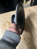
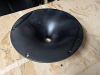
P.S.: Where did you get your waveguide printed? Surface finish is looking nice.
@fluid could tell you if @kimmosto restricted this concept to second order crossovers. From simulations with Ath, I found that 1.2 lambda is optimal for a less abrupt transition between waveguide and woofer, despite that I simulated the a crossover in VCad that is asymmetric, fourth order on the tweeter, third order on the woofer.
If you want to know it, you can download the ABEC project of ST260B from mabat's page and have yourself a full set of polars calculated. You can then import them in VCad. You would only need to create a simulation of a 12-inch woofer in a box with Ath, which is very simple. This data is partly incomplete, because it would not include the vertical diffraction results of the combined system, but to check which distance between the sources delivers an optimum, it is ample advice.
This is a very handy and fast forward (okay, takes a while to simulate but then) approach.
P.S.: Where did you get your waveguide printed? Surface finish is looking nice.
Thanks diyiggy, AllenB and sheeple. Correct way for me seems to be to make test baffle and measure my own data and simulate them in Vcad to find correct spacing for final baffle. I tried to open st260 project in ABEC but got some solving and observation errors. Im not familiar with this app.
I have three different 12" woofers for test with ST260B: 12pr320, Peerless SLS12 and Audax with wonderful name: HIF 30 HSM C 2 CA 14.
Sheeple: "P.S.: Where did you get your waveguide printed? Surface finish is looking nice."
Thanks, my friend printed them and there was some sanding before glueing halfs together. Still some finishing ahead to get glue seam disappear.

It is not restricted to second order crossovers, but it would generally be more applicable to in phase crossovers as the 3rd order types will have a phase mismatch and this can have the same sort of effect on being able to smooth out the in room and power curves by moving the vertical nulls around. I don't imagine that they will significantly change the general advice either though.
This seems to make the most sense as working with real data is better. The general idea is to avoid the 0.5 to 0.7 W/L distances. With DI matched drivers 0.5 W/L CTC gives the worst power response. In most cases it is hard to get under 0.5 W/L so moving out to 1 to 1.4W/L can be a better compromise. As your closest distance is 1 W/L I don't see a problem anyway.Correct way for me seems to be to make test baffle and measure my own data and simulate them in Vcad to find correct spacing for final baffle.
Thanks Fluid, Im going with this plan.This seems to make the most sense as working with real data is better. The general idea is to avoid the 0.5 to 0.7 W/L distances. With DI matched drivers 0.5 W/L CTC gives the worst power response. In most cases it is hard to get under 0.5 W/L so moving out to 1 to 1.4W/L can be a better compromise. As your closest distance is 1 W/L I don't see a problem anyway.
Yeah its about smoothing out DI. With freestanding waveguide its easy as one can move it after building the system. If waveguide was on baffle the position needs to be desided before measurements and simulation. Just measure the system, simulate xo, use the coordinate system to move the waveguide around to have smoothest response. Not too nuch magic, just driving the simulator until best outcome, what ever that is for the measurements, for the construct.
Does it smooth the DI only in vertical plan ?
@Oceanw ,With the B baffled version I should be concerned also by the horizontal offset between two driver for phase integration if made passive... The mezzo calapamos description by Humblehomemadehifi shows it has to advance sligty the horn mouth for proper phase in the passband. Yours being less deep it could be different, so two box construction sounds like a nice choice...
@Oceanw ,With the B baffled version I should be concerned also by the horizontal offset between two driver for phase integration if made passive... The mezzo calapamos description by Humblehomemadehifi shows it has to advance sligty the horn mouth for proper phase in the passband. Yours being less deep it could be different, so two box construction sounds like a nice choice...
Last edited:
Yes, when you measure each driver rotating on its on-axis like in the measurement manual then you would change the coordinates to reflect the build construct as per same measurement manual.
Then, if it is a prototype box and you plan to build the real one so that the c-c can be changed in reality, you may very well deviate from the actual build driver positioning in the simulator for extra design freedom, like changing the Y coordinate to find smoothest c-c for crossover frequency that might have other constraints to it. Play with the simulator, practice taking measurements and how to process them for simulation. Don't be afraid of building several prototypes, each is possibility to tweak multiple parameters / weed out issues. And have fun!🙂
Then, if it is a prototype box and you plan to build the real one so that the c-c can be changed in reality, you may very well deviate from the actual build driver positioning in the simulator for extra design freedom, like changing the Y coordinate to find smoothest c-c for crossover frequency that might have other constraints to it. Play with the simulator, practice taking measurements and how to process them for simulation. Don't be afraid of building several prototypes, each is possibility to tweak multiple parameters / weed out issues. And have fun!🙂
Thanks tmuikku. I made earlier basic turning table and semi-dual channel measurements can be done 👍Yes, when you measure each driver rotating on its on-axis like in the measurement manual then you would change the coordinates to reflect the build construct as per same measurement manual.
Then, if it is a prototype box and you plan to build the real one so that the c-c can be changed in reality, you may very well deviate from the actual build driver positioning in the simulator for extra design freedom, like changing the Y coordinate to find smoothest c-c for crossover frequency that might have other constraints to it. Play with the simulator, practice taking measurements and how to process them for simulation. Don't be afraid of building several prototypes, each is possibility to tweak multiple parameters / weed out issues. And have fun!🙂
Work progress in Vcad have to be recalled, have forgotten for example baffle diffraction merging workflow. Hope someday there would be better videos for newest Vcad. And if there ever will be fundraiser for developer of new Vcad tutorial videos, I would immediately join with 50usd 🙂
Quick info, which I think might help prevent confusion with it 🙂 VituixCAD is a tool where you can load set of measurements, so called spinorama. You can load multiple sets into one simulation, each set is represented by "driver" in main program. Usually its one set of vertical and horizontal measurements for each driver but could be anything else one has imagination for. One set of measurements could be from multiple drivers for example, or simulated in diffraction tool with ideal drivers. Its your responsibility to provide properly made data and set it up in the simulator so that the simulation would reflect reality. On beginning its good to stick with the recommended methods found in the measurement manual. Thats that.
Now, how to get set of measurements? VituixCAD measurement manual explains how to get reasonably accurate measurements at home and understanding what this is helps you to navigate all of it through. You could get very good measurements in real anechoic chamber but that is very expensive service for hobbyist use.
To get reflection free measurements at home, that would reasonably accurately represent acoustic output of your speaker, we need to use windowing with the measured responses, cut the signal before reflections of room arrive to microphone. On a typical home this is something like 4ms window. Such short time window means low frequencies don't have time to pass it so we don't have sufficient data for frequencies who are longer than about half the window, basically measurement resolution gets very poor below ~500Hz. You could measure outside, far from buildings and elevate speaker high up in the air to get longer window and more resolution but this is cumbersome and not often possible due to urban noise.
So, here is the trick, to get resolution to low frequency we can take a nearfield measurement right at the cone to have reflections relatively low level compared to direct sound, import that to diffraction tool and simulate the far field response! Then there is the merge tool where you then stitch the poor resolution windowed real measurements with the simulator generated measurements.
Hope it helps 🙂
Last edited:
Yes, I´ve done like this earlier 👍Quick info, which I think might help prevent confusion with it 🙂 VituixCAD is a tool where you can load set of measurements, so called spinorama. You can load multiple sets into one simulation, each set is represented by "driver" in main program. Usually its one set of vertical and horizontal measurements for each driver but could be anything else one has imagination for. One measurement could be from multiple drivers for example, and its then your responsibility to properly handle the data and set it up in the simulator for the simulation to reflect reality. On beginning its good to stick with the recommended methods found in the measurement manual. Thats that.
Now, how to get set of measurements? VituixCAD measurement manual explains how to get reasonably accurate measurements at home and understanding what this is helps you to navigate all of it through. You could get very good measurements in real anechoic chamber but that is very expensive service for hobbyist use.
To get reflection free measurements at home, that would reasonably accurately represent acoustic output of your speaker, we need to use windowing with the measured responses, cut the signal before reflections of room arrive to microphone. On a typical home this is something like 4ms window. Such short time window means low frequencies don't have time to pass it so we don't have sufficient data for frequencies who are longer than about half the window, basically measurement resolution gets very poor below ~500Hz. You could measure outside, far from buildings and elevate speaker high up in the air to get longer window and more resolution but this is cumbersome and not often possible due to urban noise.
So, here is the trick, to get resolution to low frequency we can take a nearfield measurement, import that to diffraction tool and simulate the far field response! Then there is the merge tool where you then stitch the poor resolution windowed real measurements with the simulated ones.
Hope it helps 🙂
Im wondering will baffle step loss of 380mm wide baffle be visible in 1m measurements or should I merge diffration simulated response on the top of already merged far and near measurements. Hmm.. too early to speculate this, shall measure first and check after that. And apologies for diyiggy for offtopic and hijacking your thread! There will be one week delay for this project due to work and I will post measurements when done that relate this thread topic
Simulated baffle diffraction should only be added to half space measurements like near field. 1 m is not really truly in the far field for most speakers but it is a reasonable compromise if measuring in a small room. If not measure further away but don’t add baffle diffraction to what is meant to be a far field response.Im wondering will baffle step loss of 380mm wide baffle be visible in 1m measurements or should I merge diffration simulated response on the top of already merged far and near measurements. Hmm..
This thread might help you out
https://www.audiosciencereview.com/...ents-spinoramas-with-rew-and-vituixcad.21860/
A while ago, I posted a Spreadsheet for calculating driver beaming / directivity / dispersion / beamwidth that you may find useful.
Measured 12PR320 and Peerless DFM-2535R00-8 in ST260B horn.
Heres for start 12PR320 horizontal measurements from 1000mm distance. Any tips what scaling/limits in REW should be used?

Heres for start 12PR320 horizontal measurements from 1000mm distance. Any tips what scaling/limits in REW should be used?
- Home
- Loudspeakers
- Multi-Way
- 12" & >=90° Horn : where to cross over?