Thanks Rod - you can always be relied on to give a full explanation of how these things work in theory and practice.
I've made a draft diagram - is this correct or what needs to be altered?
I have a friend who will be using a SMPS supply for a 10Y stage, and he will be interested to see this and may comment.

I've made a draft diagram - is this correct or what needs to be altered?
I have a friend who will be using a SMPS supply for a 10Y stage, and he will be interested to see this and may comment.
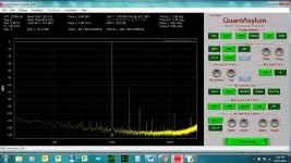
FWIW I used smps for B+ and filament bias and got pretty good results with a 71a. I did have some issue with the rca unit ground as there may have been some leakage, but after adding some input transformers for isolation and so I can have balanced in, noise was pretty much gone. I had some spurious noise at 11k and 20k+ but eventually got that sorted
Attachments
Andy, please put the 33uH and 5uF on the RC regulator side; CMC directly on the converter output. CMCs usually have some usable differential mode inductance, anyway.
BTW, Avoid adding any electrolytic caps to the converter output: even 470uF can send them out of the stable region.
Take care when drawing PE symbols. The filter PE connexions go back to the converter input PE (short loops reduce impedance, and radiated emissions).
The chassis PE will need to have a longer cable, but should not be carrying much current, thanks to the diverting filters. Ideally it will connect fairly near to the converter PE but not directly to it.
Revised draft circuit. Questions:

- as Zeta4, do the 470nf caps to PE connect to +/- before or after the CMC ?
- Is the 33uH and 5uF cap in the filament supply box as shown?
- Is there any cap before the RC regulator in the preamp box? I used to use one with the older V4 regs with a linear supply.
Yes, the circuit in #245 is correct.
The 470nF pair of caps are diverting any noise current to PE (the EMC reference); the CMC increases the series impedance. Remember, there is a cap from output + to PE internal to the converter module.
Yes, 33uH-5uF is also near the converter.
No need for a cap at the input of V9, but with V4, a 470nF Mkp helps.
I heard that DHT amplifiers sound better than indirectly heated counterparts. Is it true, and if yes, why? I think this should have been mentioned in the #1 post.
I don't know if we need to get into this argument - it gets very involved, there are many theories and few reliable explanations of what the differences actually are. The argument could go on for post after post and might well go nowhere. Maybe a separate thread?I heard that DHT amplifiers sound better than indirectly heated counterparts. Is it true, and if yes, why? I think this should have been mentioned in the #1 post.
This is a thread for DHT users, who use them because there's no doubt in their minds that they like and indeed prefer the sound.
Yes, the circuit in #245 is correct. The 470nF pair of caps are diverting any noise current to PE (the EMC reference); the CMC increases the series impedance. Remember, there is a cap from output + to PE internal to the converter module. Yes, 33uH-5uF is also near the converter. No need for a cap at the input of V9, but with V4, a 470nF Mkp helps.
Thanks Rod, very helpful. I'll set that up and report on the sound when it's working. Could be useful information for those wondering about a SMPS supply. Though it may be the case that linear will still sound superior.
Your Epcos choke should be OK, although you may get much higher L to R ratio with a gapless core. For CM choke, the more inductance the better, but you wouldn't want the choke to be too large or have too much DCR.What value CM choke? I have some Epcos 18mH, 2A. Is that in the ballpark for a 10Y or what do you suggest? Is the CM choke followed by a cap or does it go straight into the filaments or straight into Rod's reg?
Output capacitor - NO! That kills the whole purpose of chokes isolating power supply from filament. Capacitor across filament doesn't sound good. But this only applies if you don't use a regulator. Rod's regulator provides very good isolation, which makes chokes between supply and filament unnecessary.
Last edited:
Andy, I think the Pulse CMC Sridhar use has a toroidal nanocrystalline core because it has very low DCR < 150mΩ, Wurth has 2 other similar parts available through Mouser....What value CM choke? I have some Epcos 18mH, 2A...
Can the CM choke be placed after the LC filter though, making it AC->rectifier bridge->LC filter -> CM choke -> DM choke (only on + side) -> filament?Your Epcos choke should be OK, although you may get much higher L to R ratio with a gapless core. For CM choke, the more inductance the better, but you wouldn't want the choke to be too large or have too much DCR.
Output capacitor - NO! That kills the whole purpose of chokes isolating power supply from filament. Capacitor across filament doesn't sound good. But this only applies if you don't use a regulator. Rod's regulator provides very good isolation, which makes chokes between supply and filament unnecessary.
If the LC filter is well done (i.e. large inductor in the range of 0.5-1.0H + large capacitor), I wonder if there is still any need to put CM choke before the LC filter and connecting caps to the CM choke?
1:4 SUT's were mentioned in this thread as input transformer in front to help the low mu DHT. Could 1/8 watt microphone transformers be candidates? Edcor has 80% nickel core shielded models 1:5, 1:8, 1:10, 1:12 at a great price for this much Nickel. I have an order for some chokes going in and was thinking of adding a pair of these onto the order to experiment with. My DAC has balanced XLR outputs, these Edcors have +/- CT primary, but not sure if they are too sensitive or if a microphone primary is appropriate for use with a DAC. I suppose I'd put the volume control across the secondary. Am I way off course here even considering a mic xformer? (newby)
https://edcorusa.com/collections/ma...evel-matching-transformers-with-copper-shield
https://edcorusa.com/collections/ma...evel-matching-transformers-with-copper-shield
MXcs Series
Microphone Level
Max. Input: 250mVrms
THD+N: <0.01%
Frequency Response: 20~20K Hz, <1dBu
Isolation: 500Vrms
Microphone Level
Max. Input: 250mVrms
THD+N: <0.01%
Frequency Response: 20~20K Hz, <1dBu
Isolation: 500Vrms
MXcs Series
Microphone Level
Max. Input: 250mVrms
THD+N: <0.01%
Frequency Response: 20~20K Hz, <1dBu
Isolation: 500Vrms
Ah, thanks I missed that, it won't work with a DAC. Edcor does have 1:4 and 1:5 models in their XSM series, these are 2.5 watts too. And cheap to experiment with then decide if more expensive is warranted later.
https://edcorusa.com/collections/ma...-matching-transformers?variant=41246089773243
It's OK for line level.
If you perform 600R source impedance, the bandwidth will be good (some R-C snubber on the secondary may need - see 40-50kHz bump)
https://cdn.shopify.com/s/files/1/0586/3830/3419/files/Plot_XSM600-10K.pdf?v=1626816454
In US it's significantly cheaper than in EU... but now Don-Audio is in action:
https://www.don-audio.com/Edcor-XSM600-10K
Generally that's true, but shopping for the Hammond 1:4 input transformer that Andy recommended, I found the best deal in Germany, shipping to the US included.In US it's significantly cheaper than in EU...
I would like to return to the question of choke filtration, specifically, the point of using this design "properly" for filament supplies.
Given the level of filtration/regulation afforded by the LCLC configuration and that afforded by a VERY quiet voltage regulator, is using them both on a filament supply redundant? And if so, which part is redundant, the regulator? or the LCLC filter?
Given the level of filtration/regulation afforded by the LCLC configuration and that afforded by a VERY quiet voltage regulator, is using them both on a filament supply redundant? And if so, which part is redundant, the regulator? or the LCLC filter?

- Home
- Amplifiers
- Tubes / Valves
- All-DHT amplifiers: no indirectly heated signal tubes!