Hi Jan,
Great achievement that you got this far, now being able to play music over your DD amps.
When I got it right, you have the option to switch between DD and the original transformers, true ?
If so, it would be very interesting to see the acoustic frequency responses of both ways.
FR’s don’t tell the whole story, but nevertheless they would be very interesting to compare.
Hans
Hi Demian,
That's a smart thing, I will check that out!
I wasn't sure they did a lot in that particular setup, the room was large enough to place the ESLs10 ft from the back.
But at home it is less, plus there the rear boundary is mostly glass.
I'll post a pic when I get back home.
Jan
That's a smart thing, I will check that out!
I wasn't sure they did a lot in that particular setup, the room was large enough to place the ESLs10 ft from the back.
But at home it is less, plus there the rear boundary is mostly glass.
I'll post a pic when I get back home.
Jan
I'll see if I can do that, yes. What I already did was run Dirac Live! Room Correction and I noticed that the response, untreated, was relatively flat in my room, no major dips or peaks. The Room Correction did not make a big difference either; the only detectable difference (by me) was a slight improvement in sound stage. Maybe I just lucked out in my room, it's an old converted chocolate factory (really!) with ceilings of 4.60 meters.Hi Jan,
Great achievement that you got this far, now being able to play music over your DD amps.
When I got it right, you have the option to switch between DD and the original transformers, true ?
If so, it would be very interesting to see the acoustic frequency responses of both ways.
FR’s don’t tell the whole story, but nevertheless they would be very interesting to compare.
Hans
Jan
When it comes to back side reflections i want to give some advice.
If you have 2,5> meters (equals 15 mS) of air behind the panels your brain will blend in the reflections as part of the recordings reflections.
After many years of testing different acoustic treatments me and some friends (with QUADS.... ) has found that the number one rule is to move the speakers avay from the back wall, and move yourself closer to tha wall behind you.
The bass responce will improve a lot, and the music will get released from the speaker and just appear in the middle of the room.
Next step is to absorb the first reflections from side walls, floor and roof. And behind your head! Thats it. If you have achieved this you can experiment with absorption behind the speaker... but most likely you will discover the blending with the room will be less effective.
Maybe there should be a separate thread about how to treat electrostatic speakers in a room.
Quite different from box speakers.

On slide 8 you have a Quiz.... would it be possible to reveal any theories or even conclusions?
When you go in "normal" mode with the tranformers... are you using the original 220uF cap?
Is there any component except the transformer that can cause the distortion?
Are you using the clamping board in both setups?
Thanks a LOT for your winformation.
The OTL project that I have is using a 1:3 stepup transformer and a capacitor between driving stage (300B) and output tubes (GM70) .
Well, during the presentation the majority (including some xformer specialists) was of the opinion that it could only be the step-up transformer.
I did not make any change to the 'normal' setup.
That clamping board question is a very good one - I need to open a speaker to see how that connection was exactly.
Jan
I did not make any change to the 'normal' setup.
That clamping board question is a very good one - I need to open a speaker to see how that connection was exactly.
Jan
Yes, that DC resistance makes sense. They can vary a bit though, like their winding pattern isn't super well controlled.
Sheldon
Sheldon
The early generation clamp board actually crowbarred the audio input. Good for destroying more than a few amps. It would have no effect on a direct drive and the SCR should have little impact when off on any amp. Later quads added a limiter board with a stack of Zeners which can be quite nonlinear. Personally I think MOV's would be the ideal limiter in this application. In my measurements they are really benign until you reach the breakdown voltage and they have much more energy clamping than Zeners.
I think what @esl 63 was hinting at is that a crowbar or limiter at the stator side would have relatively large impact due to the high impedance levels there.
In my dd amp the levels are naturally limited to the HV supply so a clamp should not be necessary.
I have a small side project to investigate a soft clipping provision for the amp.
Jan
In my dd amp the levels are naturally limited to the HV supply so a clamp should not be necessary.
I have a small side project to investigate a soft clipping provision for the amp.
Jan
Hans you mean acoustic response as measured by a mike?Hi Jan,
Great achievement that you got this far, now being able to play music over your DD amps.
When I got it right, you have the option to switch between DD and the original transformers, true ?
If so, it would be very interesting to see the acoustic frequency responses of both ways.
FR’s don’t tell the whole story, but nevertheless they would be very interesting to compare.
Hans
If the electrical response at the stators is identical, would you not expect the acoustic response to be identical too?
Jan
Good question that makes sense.Hans you mean acoustic response as measured by a mike?
If the electrical response at the stators is identical, would you not expect the acoustic response to be identical too?
Jan
However in such a complex transfer from voltage input to sound output, I’m not sure wether this is true in this case.
Ultimately it would mean that DD has no benefit over the transformer solution, wouldn’t it ?
Hans
In the slides I posted there is also a THD comparison. The step-up gives about 35dB more THD than the DD. That is most likely from the step-up xformer as the used amps (my own paX and a Purify) have much better performance on a 'normal' speaker load.
You can make the point that the difference between -76dB THD and -110dB THD may not be audible.
Yet, in listening sessions at the ETF, I always got the same response, that details in the DD were much better.
Independently from each other, listeners mentioned the 'bouche' with blowed instruments being much better.
Not double blind or anything, and maybe they just wanted to be nice to me, but the similarity of comments was striking.
Jan
That’s exactly my point.In the slides I posted there is also a THD comparison. The step-up gives about 35dB more THD than the DD. That is most likely from the step-up xformer as the used amps (my own paX and a Purify) have much better performance on a 'normal' speaker load.
You can make the point that the difference between -76dB THD and -110dB THD may not be audible.
Yet, in listening sessions at the ETF, I always got the same response, that details in the DD were much better.
Independently from each other, listeners mentioned the 'bouche' with blowed instruments being much better.
Not double blind or anything, and maybe they just wanted to be nice to me, but the similarity of comments was striking.
Jan
Voltage response is the same but sound perception is different.
That’s why I’m curious wether this difference will be reflected in the acoustic frequency response.
Hans
Hans, I don't think that you'll see the difference between -76 dB THD and -110 dB THD in an acoustic freq response.
But I'll do some measurements when I get some time.
Jan
But I'll do some measurements when I get some time.
Jan
Agreed, two different animals, distortion and freq response.Hans, I don't think that you'll see the difference between -76 dB THD and -110 dB THD in an acoustic freq response.
But I'll do some measurements when I get some time.
Jan
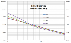
I have attached distortion measurements from a Danish magazine where they inserted a 1R resistor in series with the ESL and measured the distortion caused by the nonlinear load presented by the transformer. Measurements are with rumble filter and voltages shown are peak voltages.
Also, my own measurements, the second attachment, now without rumble filter and with rms voltages, come to the same ca. -84dB@500Hz distortion, independent of level when driven from a very low distortion Amp such as yours.
Extrapolating the 6dB/oct distortion line to 1Khz would result in -90dB THD@1Khz. So, -76dB@1Khz distortion at the secondary side seems to be a good result.
Also quite revealing with these distortion measurements is that they are predominantly 3rd harmonic.
And yes, uneven harmonics can cause nasty auditory side effects, but I doubt whether anybody can hear this level of 3rd Harm distortion, but I may be wrong.
Take also into account that the ESL is adding extra distortion
Analyzing a .Wav file recorded at the same at 1KHz with DD and trafo driven could answer that question how distortion compares between the two.
I think you did a magnificent job, just being curious how this translates into acoustic measurements.
Hans
P.S. the PDF from the Danish magazine was too big to attach but was practically identical to my measurement.
Attachments
Last edited:
I am building a bal to se converter board as an add-on to the 1:1000 HV attenuator, that I plan to use to record long term levels when playing music, for interest in clipping behaviour.Agreed, two different animals, distortion and freq response.
I have attached distortion measurements from a Danish magazine where they inserted a 1R resistor in series with the ESL and measured the distortion caused by the nonlinear load presented by the transformer. Measurements are with rumble filter and voltages shown are peak voltages.
Also, my own measurements, the second attachment, now without rumble filter and with rms voltages, come to the same ca. -84dB@500Hz distortion, independent of level when driven from a very low distortion Amp such as yours.
Extrapolating the 6dB/oct distortion line to 1Khz would result in -90dB THD@1Khz. So, -76dB@1Khz distortion at the secondary side seems to be a good result.
Also quite revealing with these distortion measurements is that they are predominantly 3rd harmonic.
And yes, uneven harmonics can cause nasty auditory side effects, but I doubt whether anybody can hear this level of 3rd Harm distortion, but I may be wrong.
Take also into account that the ESL is adding extra distortion
Analyzing a .Wav file recorded at the same at 1KHz with DD and trafo driven could answer that question how distortion compares between the two.
I think you did a magnificent job, just being curious how this translates into acoustic measurements.
Hans
P.S. the PDF from the Danish magazine was too big to attach but was practically identical to my measurement.
Maybe that can be used to analyze .wav files played?
(I made a bad mistake on the 1st board so waiting for Eurocircuits to deliver the corrected version).
Jan
- Home
- Loudspeakers
- Planars & Exotics
- QUAD 63 (and later) Delay Line Inductors