I'm sure my grandfather has something in stock 🙂If you have at hand a dynamic earphone like those used for cell phones or the oldest "walkmans" it will act as a microphone too. Careless its size.
After testing, he may land me his aux mic for super8 camera.
Perfect. Save the 27mm for the final tank and can use the 20mm for the oscillator.
For the mic, use those that have an unit unusable. Don't break one for the task...
Let's do as follow: take the 20mm diammeter tube and make in it a couple of narrow holes in the same line from one end to the other 12mm appart (refer to the post 117 of the FM thread). No more than 1mm diameter each hole. It may be punctured with a nail or a pin. Thus insert one end of the copper wire through it. Let it go to one end of the tube and let, say, 4cm to wire it to the circuit previously removing the enamel. Thus, with the rest of wire, turn about 15 to 20 turns around the tube having the wire very tense. Thus, insert the wire in the other hole and return by inside of the tube close to the first end. Make the coil near the center of the tube and adjust turn separation so it are properly distributed across the long of the coil.
It is difficult to explain with words. If I am not explicit or clear, I may take some serial pics to satisfy. I have those coils stil saved.
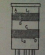
Perhaps this pic may help me explain. You will have one coil in place of two and ignore the pins at the base. In our case points A and B must be in the same imaginary line from top to bottom.
For the mic, use those that have an unit unusable. Don't break one for the task...
Let's do as follow: take the 20mm diammeter tube and make in it a couple of narrow holes in the same line from one end to the other 12mm appart (refer to the post 117 of the FM thread). No more than 1mm diameter each hole. It may be punctured with a nail or a pin. Thus insert one end of the copper wire through it. Let it go to one end of the tube and let, say, 4cm to wire it to the circuit previously removing the enamel. Thus, with the rest of wire, turn about 15 to 20 turns around the tube having the wire very tense. Thus, insert the wire in the other hole and return by inside of the tube close to the first end. Make the coil near the center of the tube and adjust turn separation so it are properly distributed across the long of the coil.
It is difficult to explain with words. If I am not explicit or clear, I may take some serial pics to satisfy. I have those coils stil saved.
Perhaps this pic may help me explain. You will have one coil in place of two and ignore the pins at the base. In our case points A and B must be in the same imaginary line from top to bottom.
Attachments
Last edited:

Ok, I read thru multiple times while looking at the picture, I think that I understand.Perfect. Save the 27mm for the final tank and can use the 20mm for the oscillator.
For the mic, use those that have an unit unusable. Don't break one for the task...
Let's do as follow: take the 20mm diammeter tube and make in it a couple of narrow holes in the same line from one end to the other 12mm appart (refer to the post 117 of the FM thread). No more than 1mm diameter each hole. It may be punctured with a nail or a pin. Thus insert one end of the copper wire through it. Let it go to one end of the tube and let, say, 4cm to wire it to the circuit previously removing the enamel. Thus, with the rest of wire, turn about 15 to 20 turns around the tube having the wire very tense. Thus, insert the wire in the other hole and return by inside of the tube close to the first end. Make the coil near the center of the tube and adjust turn separation so it are properly distributed across the long of the coil.
It is difficult to explain with words. If I am not explicit or clear, I may take some serial pics to satisfy. I have those coils stil saved.
Perhaps this pic may help me explain. You will have one coil in place of two and ignore the pins at the base. In our case points A and B must be in the same imaginary line from top to bottom.
Basicly I need to make a hole where coil starts and where coil ends, and another two holes to feed the wire thru one more time to keep the tension. This would be it right? Like on that photo. This will be a single coil and I don't need to spare the space for second one, right?
Attachments
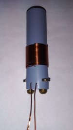
Done.Excellent. The brass piece inside the coil and the screws are optional. Choice any convenient method to fix the coil to the chassis.

In case you will need to find such pvc pipes these are couplers for pvc pipes for electric installations in garages, basements and such. Few cents each. They are a bit soft but not too much.
I will fix the coil to the board with zip tie for now as I will rebuild on chassis when the prototype is finished. I like your method for fixing it
Last edited:
Perfect. Next steep is nude the copper wire and hook it into the oscillator. Thus it is the new squematic. Use the gang that you had in series to the Xtal, now across the coil. Use the local oscillator section that has lower capacitance than the signal one.
To put it in service, turn the gang into the higher capacity end (counter clock wise). Power on the oscillator and the monitoring radio. Slowly turn the gang until it starts to oscillate.
As you continue rocking the gang, the oscillator may stop again. Thus leave it in a position where the oscillation was stable. Try 4 or 5 times to familiarize with its behavior. Then, switch off the oscillator and leave it cool down. After say, 5 minutes start it again to see if it is capable of self starting. Sometimes this circuit is a bit stubborn.
Attachments
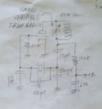
Ok. I will start with the build now. Only thing I don't understand is: "Use the local oscillator section that has lower capacitance than the signal one."Perfect. Next steep is nude the copper wire and hook it into the oscillator. Thus it is the new squematic. Use the gang that you had in series to the Xtal, now across the coil. Use the local oscillator section that has lower capacitance than the signal one.
To put it in service, turn the gang into the higher capacity end (counter clock wise). Power on the oscillator and the monitoring radio. Slowly turn the gang until it starts to oscillate.
As you continue rocking the gang, the oscillator may stop again. Thus leave it in a position where the oscillation was stable. Try 4 or 5 times to familiarize with its behavior. Then, switch off the oscillator and leave it cool down. After say, 5 minutes start it again to see if it is capable of self starting. Sometimes this circuit is a bit stubborn.
Is this what you mean:
I need move current gang to the across the coil. Ok...
Then I need to get smaller trimmer from radio such as this one:

And connect it across the crystal?
My bad, I was looking at the wrong schematic. Now I understand everything clearly. Will build & test & report.I wrote 22 and 220pF. Those values aren't critical. If you have 18pF, use it. Have 27pF, usi them too. Same to the 220pF unit.
Plastic gangs has to sections with a common ground and shaft. The oscillator section has lower capacitance than the signal one.

Oh this is it. Thank you.From left to right: signal (Big C), ground and osc (Lower C).
Will do. Just one more thing.... 100k is on the b+... If I bring 150v from the psu do I need it?Enjoy. Use a plastic knob for the variable gang: both terminal will be live for AC & DC. AC is small but DC may be 150V.
I cant hear it on the radio.Eventually if the oscillator performs good, we can reduce its value in order to increase plate current spike and thus the excitation for the pentode.
Voltages:
B+ 216v
Grid -0.74v
Plate 54v
Last edited:
No, One time screen voltage was 1.20v and it lowered toward 0.75v as I was turning the gang from left to right... only once... now it sits at 0.74 no matter the gang position... I had triple checked the wiring.At no one position of the gang?
- Home
- Amplifiers
- Tubes / Valves
- Help me put these tubes into good use... I need a project