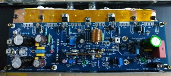
Just a quick photo (beauty shot? 😁) of another channel running after I updated the cap multiplier section from the latest build guide.
- Daniel

Good photo. What really bothers me is the split heatsink. This creates a strong thermal imbalance.
Hi Ralf,Good photo. What really bothers me is the split heatsink. This creates a strong thermal imbalance.
Thanks, I know what you are saying and felt the same way. But the Wolverine amp has NPN, PNP, NPN, PNP, interleaved on each heat sink, also the brackets thermally couple the heatsink a bit, as does the close-ish fit between the two. If it really bothers you, you can use a copper "heat spreader plate" or aluminium plate. But I can say in practice after using 5 or 6 of these cases as long as you spread the transistors evenly over the two heatsinks it is really not an issue.
Hope this helps.
- Daniel
When I built the Honey Badger, under Stuart's suggestion, I put a copper bar between and above the two split heatsinks, on which I mounted the output devices. But Honey Badger has separate PNP and NPN transistors. As you stated above, Wolverine is different.Hi Ralf,
Thanks, I know what you are saying and felt the same way. But the Wolverine amp has NPN, PNP, NPN, PNP, interleaved on each heat sink, also the brackets thermally couple the heatsink a bit, as does the close-ish fit between the two. If it really bothers you, you can use a copper "heat spreader plate" or aluminium plate. But I can say in practice after using 5 or 6 of these cases as long as you spread the transistors evenly over the two heatsinks it is really not an issue.
Hope this helps.
- Daniel
Gaetano.
Attachments
Last edited:
The copper bar could be used and is a great idea but I have done quite alot of measurement on the Wolverine without any problems so far.When I built the Honey Badger, under Stuart's suggestion, I put a copper bar between and above the two split heatsinks, on which I mounted the output devices. But Honey Badger has separate PNP and NPN transistors. As you stated above, Wolverine is different.
Gaetano.
Personally in this case I don't think it is necessary.
- Daniel
Yeah, I saw all your videos and I totally agree with you. I'm building the Wolverine exactly the way you did!
Gaetano.
Gaetano.
Right. But is it so hard to make such wide heatsinks for Modushop? It is technically possible, there are many photos of amps that are 30 or 40 cm deep.Hi Ralf,
Thanks, I know what you are saying and felt the same way. But the Wolverine amp has NPN, PNP, NPN, PNP, interleaved on each heat sink, also the brackets thermally couple the heatsink a bit, as does the close-ish fit between the two. If it really bothers you, you can use a copper "heat spreader plate" or aluminium plate. But I can say in practice after using 5 or 6 of these cases as long as you spread the transistors evenly over the two heatsinks it is really not an issue.
Hope this helps.
- Daniel
Hi Ralf,
Trust me, if these heatsinks were something easy to obtain we would have purchased them a long time ago since I know there is a huge request for them.
Main problem is it's a lot more expensive to buy a single 400mm heatsink than 2 separate 200mm and our supplier hardly produces them because of that.
I've had other members tell me about the thermal imbalance and the solution they've come up with is something similar to what Daniel suggested: they've had us mill some 10mm thick "heat spreader plates" which are mounted on the flat surface of the heatsinks and cover a good part of so they could mount their components on top of them.
If you can share pictures of this I would be interested. As an off topic for certain class A amplifiers (i.e. Aleph 60) in a 4U/500 chassis (i.e. two 250mm heatsinks), it can be beneficial!Hi Ralf,
Trust me, if these heatsinks were something easy to obtain we would have purchased them a long time ago since I know there is a huge request for them.
Main problem is it's a lot more expensive to buy a single 400mm heatsink than 2 separate 200mm and our supplier hardly produces them because of that.
I've had other members tell me about the thermal imbalance and the solution they've come up with is something similar to what Daniel suggested: they've had us mill some 10mm thick "heat spreader plates" which are mounted on the flat surface of the heatsinks and cover a good part of so they could mount their components on top of them.
Best,
Anand.
Good photo. What really bothers me is the split heatsink. This creates a strong thermal imbalance.
Take this with the usual (large) grain of salt, but in my EF3-3 build (3U 400mm chassis, 500 VA toroid, +/- 48.5 VDC rails) the heatsinks were barely warm and certainly not hot after playing 24/7 for 3 days.
Regards.
You don’t recall where the bias is set do you? (mA I assume).Take this with the usual (large) grain of salt, but in my EF3-3 build (3U 400mm chassis, 500 VA toroid, +/- 48.5 VDC rails) the heatsinks were barely warm and certainly not hot after playing 24/7 for 3 days.
Regards.
Best,
Anand.
Hi Guy's,
I just posted a small update to the bom. Please download it from your Dropbox link when you have time.
This update applies to the 2nd GB boards only.
Update is noted in the revisions area at the bottom of the file.
I just posted a small update to the bom. Please download it from your Dropbox link when you have time.
This update applies to the 2nd GB boards only.
Update is noted in the revisions area at the bottom of the file.
If you can share pictures of this I would be interested. As an off topic for certain class A amplifiers (i.e. Aleph 60) in a 4U/500 chassis (i.e. two 250mm heatsinks), it can be beneficial!
Best,
Anand.
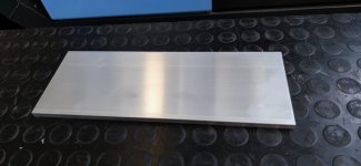
Of course, here it is. This is basically a raw, non-anodized panel for the MiniDissipante 3U which covers most of the surface of the MonoBlock heatsinks
I'll let our friend Max jump in as he purchased them recently and plans to mount them on the MonoBlock chassis so he can give you some better feedback about this 🙂 @MEPER
Attachments
Anand:You don’t recall where the bias is set do you? (mA I assume).
My recollection is that the output transistor bias across TP101 and TP102 would bounce around a bit until the amp warmed up and then would settle down to about 43 mV. DC offset also vacillated but I was able to dial it in so that after the amp had been running for a while, offset on both channels ended up below 0.6 mV.
It was fun chatting with you at Burning Amp. Good luck with your Wolverine!
Regards,
Scott
I will use two similar pieces of aluminum, 10 X 125 X 295 mm, in my Dissipante 300 4U housing, this for other reasons. It will enable me in the future to experiment with different amplifier designs, using the same housing, supply and auxiliary circuits. If it was offered as an option, drilled and tapped, I would not have to worry about destroying the heatsinks.This is basically a raw, non-anodized panel for the MiniDissipante 3U which covers most of the surface of the MonoBlock heatsinks
Okay to experiment, but that's not the way. The thermal transition resistances are enormous. Thermal paste doesn't help either.
I am highly confident that it will work as expected.
As a bonus everything to do with mentioned housings brings back happy memories about Bologna and its surroundings, amazing Florence, romantic Venice, stunning Pisa and the trill of test driving a Ferrari.
As a bonus everything to do with mentioned housings brings back happy memories about Bologna and its surroundings, amazing Florence, romantic Venice, stunning Pisa and the trill of test driving a Ferrari.
Pffttt, Ferrari are just shopping trolleys for the rich. Bologna's real claim to fame is Ducati
I am highly confident that it will work as expected.
As a bonus everything to do with mentioned housings brings back happy memories about Bologna and its surroundings, amazing Florence, romantic Venice, stunning Pisa and the trill of test driving a Ferrari.
I will use two similar pieces of aluminum, 10 X 125 X 295 mm, in my Dissipante 300 4U housing, this for other reasons. It will enable me in the future to experiment with different amplifier designs, using the same housing, supply and auxiliary circuits. If it was offered as an option, drilled and tapped, I would not have to worry about destroying the heatsinks.
View attachment 1109717
Please go ahead if you like. But this is unnecessary. Guy's please remember if its not in the build guide then its not required. We as a group have tested this and know its not necessary.
- Home
- Amplifiers
- Solid State
- DIY Class A/B Amp The "Wolverine" build thread