I might have missed it (sorry if you already answered this) - which daughter boards have you listened to and which seems to be your favorite?After about 20 hours of listening/burning in...
I'm in the process of rediscovering my music collection and it tells everything. With this amp, the instruments have a response behavior that was previously unknown to me. The whole thing sounds... different. Much better different. My best power amp so far 😍
Many thanks @Nelson Pass for everything, @Mark Johnson and @6L6 Jim for this iteration of the amp, and of course @ everyone on the forum for the help and support

As Mark wrote it is the Mountain View, I have no other IPS cards so far. But today I ordered the parts for the Tucson with an LT1122 (and the parts for the speaker protection and the chassis), so hopefully I can tell more about it in a week or so. And further cards are planned.I might have missed it (sorry if you already answered this) - which daughter boards have you listened to and which seems to be your favorite?
Last edited:
I have sourced all the parts to build a M2X. This will be my first real attempt at building from a schematic. Something I've noticed (and caused confusion in the past with my f5 build) is that occasionally parts are shown in mirror image. For example, Q5 on the main board of the M2X. Is there a reason for this? Or are schematics typically drawn from the bottom of the board?
Q5 is not mirrored. When you place it into the board from the "script" side, pin 1 must be where the square soldering field is (red dot):I have sourced all the parts to build a M2X. This will be my first real attempt at building from a schematic. Something I've noticed (and caused confusion in the past with my f5 build) is that occasionally parts are shown in mirror image. For example, Q5 on the main board of the M2X. Is there a reason for this? Or are schematics typically drawn from the bottom of the board?
I understand that the dot on the 4N35 is pin 1, and going counterclockwise from pin 1, each pin is labeled: 2,3,4,5,6. Component placement on the board is clear. On the schematic, pin 1 is shown to be at the top right rather than the top left - a mirror image of the 4N35.

98% of schematic diagrams that include ICs, use "symbols" for the ICs which have scrambled pin order. In fact that's why these schematics include pin numbers at all -- because the pin number is extremely significant electrically, while the (scrambled) pin order on the schematic symbol is electrically insignificant. Schematic symbol pin order is either utterly random, or else chosen to make the draftsman's life easy. The schematic READER's life is made easy by including the actual pin numbers.
Thank you Mark. This is part of the 'grammar' of schematics, to allow a simpler drawing. If I see numbers, ignore the drawing.
Hi,
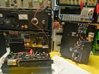
some further progress, in fact only the rear and front plates are missing, they should arrive early next week.
In the middle are the two separate local cap banks with 2x 2x33mF, and the protection circuit.

some further progress, in fact only the rear and front plates are missing, they should arrive early next week.
In the middle are the two separate local cap banks with 2x 2x33mF, and the protection circuit.
About a year ago the left channel on my DIY First Watt M2X stopped working, I was not in a good place at the time and couldn't be bothered fault finding so just swapped it out.
Yesterday I decided it was time to investigate, Opened the lid and the -24v rail to left channel had a burnt wire and connector at the PSU end.
Disconnected the wire and powered up to measure the rails, all good. Visual inspection of the left channel showed the 0.47ohm resisters were slightly browned, not a problem.
I removed the MOSFETS and tested them, all good, so I refitted them.
I swapped the opto coupler as I had a spare. Glad I fitted sockets now.
So I repaired the wire and on checking the screw in connector blocks I noticed that they were not very tight, tightened them all, checked for any visual probs on the PSU before powering up.
Long story short, it is now back in my system and working as it should.
Lesson learned: Loose connections cause heat problems at the joint.
From pre amp to speakers my system is all DIY except cables.
Akitika MM phono, Elekit TU8500 pre, M2X power, DIY TL sub, LK1 stand mount speakers.
Loving what it does.
🙂I just finished my M2x variation, working with old TAMURA transformer, fantastic sound !
Attachments
Last edited:
I asked bisesik (Ivan) that what type transformer he could to build instead of Edcor to M2x.
He wrote that its would 2 version like the DAC-s, smaller (cheaper) and bigger(expensive) size. The price is...🙂
I would like to use independent small transformer and PSU to the daughter cards. I used other amplifier's and it has huge effect.
He wrote that its would 2 version like the DAC-s, smaller (cheaper) and bigger(expensive) size. The price is...🙂
I would like to use independent small transformer and PSU to the daughter cards. I used other amplifier's and it has huge effect.
The amp in #6,111 doesn't have field-swappable input stage daughter cards, so it's more of a cloned M2 rather than M2x.
It's taken me a while to get in shape to be able to flip my M2x around to change daughter boards, back surgery didn't help. But I finally installed the Norwood board and been listening for a month. In short, it's terrific, lively, fast and detailed. Great air and revealing of venue space. Wide and deep soundstage. Preferred the system with the original B1 pre. The B1Korg was enjoyable but not as detailed and clear as B1. The Austin "diamond buffer" was very enjoyable as was the Tucson with the OPA1611 opamp, but the Norwood delivers music as I have hoped to hear it, like at an audio show. Thanks again, Mark, for this wonderful amp.
Congratulations @scranton !! I'm very glad you're experimenting with numerous DIY'ed input stages; these kinds of experiments are tons of fun and also quite eye opening.
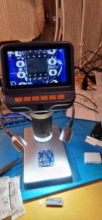
you like win easily 🙂Thanks to this project i just completed the daunting task of soldering my first smd ever, and im really excited.
All boards soldered just waiting for Keratherm to arrive and then i can try the amp out. Also waiting for some starwashers. When measuring my psu it shows +26.5 and -26.5. Is this ok or is it to much?
- Home
- Amplifiers
- Pass Labs
- The diyAudio First Watt M2x