
The speaker is all stacked up. So much effort just to put a box on top of a box!
I think it looks like a Neopolitan ice cream sandwich with the temporary baffle.
I will measure it some more this week.
...
I collect all kinds of graphs and images and need to clear some things out but thought would post before I delete them. So here is a bunch of rando stuff that I think is interesting to see:


I based many of the choices for the current speaker off these graphs.

I spent a couple of hours listening to @HeadShake 's original system and his new prototype. The new prototype has a 15" pro sound woofer in a sealed box, an 8" mid in a foamboard box, and an Audax "minimal flange" tweeter suspended in free space. We listened in mono.
I have heard the original system several times, and I remember that Headshake had it dialed in really nicely. The new prototype system had a somewhat lighter EQ in the mid bass - upper bass, but listening past that difference was relatively easy.
The main question Headshake had for me was my opinion of the space and image presentation of the prototype. I would say it was pretty spectacular for a mono system.
With the original system, the sound seemed to originate in a window about 2 ft wide and 3 ft tall around the speaker. With the new prototype, the sound seemed to come from a 6 ft x 6 ft region around the speaker. A sense of depth was more convincingly portrayed on recordings where some instruments were close-miked (vocals) and others were further away (percussion, piano). Again, we were listening to a single speaker, in mono.
Headshake is on a quest for a better presentation of sibilance consonants, such as "s" "sh" "t", "k" "th" "ch". This is not something I am particularly sensitive to, but he was able to demonstrate the superiority of the new prototype in portraying a more realistic vocal sibilance, in particular the faint echo that these sounds should make in the recording.
The original system uses high quality drivers known for their clarity and low distortion. On certain recordings I could hear more detail and clarity with the original system. Still, the inexpensive tweeter compared very well against the much more expensive Bliesma T25 beryllium. I believe the lack of a baffle contributes greatly to the performance of the Audax.
Headshake - thanks for including me in your listening evaluation.
j.
@hifijim , thanks again! It was nice to hear what you hear. After you left I was thinking how I never would have thought about a tilted mid. Now I want to measure the etons with some tilts.
(hifijim has a crazy deep well of knowledge he pulls from. He can go from talking about a 3d sim to a speaker model from XX years ago in seconds. )
I am lucky to know you and to have you down the road. (i never would be making speakers w/o hifijim)
I will try to do stereo next time with a better tweeter.
.....
while looking for a paper for another thread, I found this cool one:

They put a mic in an ear canal of a bunch of right ears. Around 3-5khz seems most similar.
https://www.ncbi.nlm.nih.gov/pmc/articles/PMC4123622/
I wish they tested some bald folks.
(hifijim has a crazy deep well of knowledge he pulls from. He can go from talking about a 3d sim to a speaker model from XX years ago in seconds. )
For sure! You helped me figure out the next direction.thanks for including me in your listening evaluation.
I am lucky to know you and to have you down the road. (i never would be making speakers w/o hifijim)
I will try to do stereo next time with a better tweeter.
.....
while looking for a paper for another thread, I found this cool one:
They put a mic in an ear canal of a bunch of right ears. Around 3-5khz seems most similar.
https://www.ncbi.nlm.nih.gov/pmc/articles/PMC4123622/
I wish they tested some bald folks.
I think you bought a Silk Dome Bliesma tweeter, what was the difference between that and Beryllium one if you compared them.
Hey.I think you bought a Silk Dome Bliesma tweeter, what was the difference between that and Beryllium one if you compared them.
I just have the t25b. I only have a bunch of smaller ones like audax, tang band, sica, ... cheap silk domes. The t25s has been in my cart many times.
(btw @hifijim .. this reminds me, that tang band tweeter was Aluminum / magnesium... i could not think of that when he was here.)
I traced the data for the real ears in the last paper and put them with the paper that measured a lab head. The equal loudness countour is there too.

blue equal-loudness c. . solid red is the average of the 7 HRTF from the right ears.

lab heads vs real heads.

Real heads with an average.
blue equal-loudness c. . solid red is the average of the 7 HRTF from the right ears.
lab heads vs real heads.
Real heads with an average.
Ok, raw data from the audax Mg on a stick.
I did some measurements moving around foam and with the ac on or off. One measurement was done with some felt scraps from another experiment. Moving things around and the AC did not change much. The felt changed things the most.


I will try the t25b on a stick next.
I did some measurements moving around foam and with the ac on or off. One measurement was done with some felt scraps from another experiment. Moving things around and the AC did not change much. The felt changed things the most.
I will try the t25b on a stick next.
T25b on a stick. The felt here stuck out like a starfish past the edge of the tweeter. This did not help anything. So it seems like if I do anything with felt it should be just to the edge.
Since the Audax Mg did best with felt I have the data from that vs the t25b.


Distortion with and without felt on the t25b;


It seems like the motor is just as much of an issue as diffraction. Ugh.
Since the Audax Mg did best with felt I have the data from that vs the t25b.
Distortion with and without felt on the t25b;
It seems like the motor is just as much of an issue as diffraction. Ugh.

Made a quick sim of a few baffle sizes-100mm,70mm, and 40mm.
This goes with the two green graphs in the previous post.
The audax looks spot on for something 100mm. The t25b does have a dip where the sim says it should around 10khz. The interesting part is the dip is -10db down and a little lower at 9500hz.
I wonder if the diffraction is happening -10db down and not at 0db is due to the material, grill, or just the shape of the sound coming off the dome. Either way, the decay is interesting in that it ignores the diffraction for a bit.
Last edited:
It is quite difficult to get accurate baffle diffraction simulations very high in frequency. The shape/thickness of the domes and surrounds together with faceplate shapes can have quite an effect. Vituix is predicting based on piston size which becomes increasingly less likely to be correct as frequency rises.
A question for polars.I wonder if the diffraction is happening -10db down and not at 0db is due to the material, grill, or just the shape of the sound coming off the dome.
Generally it is more productive to use design methods, or to use simulations with a view to reducing diffraction in the first place rather than to trying to balance what diffraction there is for a smoother plot.
This way you not only have less to worry about with regards to the accuracy of the simulations, but in general. It's good to know when you can build something without knowing the exact result, but with enough confidence that you'll simply fix what there is after measuring.
Thanks.It is quite difficult to get accurate baffle diffraction simulations very high in frequency. The shape/thickness of the domes and surrounds together with faceplate shapes can have quite an effect. Vituix is predicting based on piston size which becomes increasingly less likely to be correct as frequency rises.
I will try not to read into the 2d tea leaves too much.
Hi. I will for sure do a polar next. Thanks!A question for polars.
Generally it is more productive to use design methods, or to use simulations with a view to reducing diffraction in the first place rather than to trying to balance what diffraction there is for a smoother plot.
This way you not only have less to worry about with regards to the accuracy of the simulations, but in general. It's good to know when you can build something without knowing the exact result, but with enough confidence that you'll simply fix what there is after measuring.
I have done the workflow you describe. Simulate->buy drivers->deal with reality. It did not end up with something i liked on-axis. The phase off-axis might be why and I am still trying to figure this out.
I think 2000 to 3000hz is the issue and this is getting in the area of a small baffle size. (really the main issue is I can't put things on the walls... i rent) Like fluid said, this is all very complex and each tweeter is so different so I can't just count on the overall size to tell me what to expect. Looking at sims backward is just for curve shapes and ballpark frequencies of interest.
edit:
I should add. I was able to fix what bothers me with the small 40mm audax tweeter. It is my flawed baseline. Both hifijim and I preferred the small tweeter over the Be most of the time. It is the sparkle of the Be dome that I want back into the mix. We both heard how nice it sounded past 5khz or so.
Last edited:
^ Here is the fundamental idea what you see in the frequency response graph: We assume the transducer is good enough on its pass band so it works as almost ideal piston, hence its response ought to be flat. When you see ripple on such system response it must be secondary sound source interfering with direct sound. Secondary sound source can be from many different things and bandwidth and SPL vary. When you have felt covering the edge you've just made reflections instead of diffraction related secondary sound source. Whats different with such felt to edge diffraction is that it makes reflections instead (or at least partly). Reflections are opposite polarity than edge diffraction as secondary sound source and thus their interference pattern in frequency response is opposite.
What you essentially are set to do is eliminate any secondary sound sources to reduce the system response to that of the transducer, as good as it can be.
To get rid of secondary sound sources you must have no obstacles, no felt sticking out, and make edges disappear. If infinite baffle is not possible then the other option is make edge round over. Third option is to spread the edge, or any obstacle, so that its asymmetric enough so that the secondary sound source is as weak as possible where ever you inspect the response.
Cleanest actual speaker construct measurements I've seen is tweeter with waveguide which has proper profile and roundover (plenty in ATH thread). According to simulator a waveguide is not necessity though, for very low amount of interference on frequency response. One could achieve similar very low interference results with direct radiating tweeter as well, by having big enough roundovers. Its also debatable how audible any of this is so no need to go further than necessary.
Basically only a sphere with point source on it, or point source floating in mid air, is without hints of secondary sound sources. As we are stuck with transducer technology that has physical size and also we need some physical support structure all we have to do is approximate a sphere well enough, for the wavelengths that radiate along the structure. The shorter the wavelength the smaller roundover makes the structure behave like a sphere would, make edge disappear.
Basically one has to start roundover immediately beside a transducer to get cleanest response with smallest construct. Flat flange around a tweeter transducer prevents this and you cannot get diffraction free response unless making the roundovers silly big. Imagine the flange making flat portion to a sphere and the smaller the flat portion on a sphere is the less there is secondary sound source on the edge. Things are bad here as the flange is round, maximum interference on-axis so drastic measures needed. Simulator shows 4" diameter flat flange tweeter on a 12" diameter sphere, which makes ~33% flat portion, still shows some diffraction interference ripple. If you play with simulator you'll find out about 20% flat portion makes about no diffraction ripple. When flange is 4" diameter the whole construct would need to be 20" diameter sphere to have ~completely interference free response 🙂 If the tweeter was naked 1" without flange similar interference performance happens with only 5" diameter sphere.
In reality no such big sphere is needed. The above is just some examples to kind of show what you are chasing here.
If you apply all the above to the felt with the spikes cut on the edge the spikes would need to be similar in size as wavelength you try to distribute the diffraction with it in order to distribute secondary sound source enough to lessen its effect on-axis. If you want to use felt make features of the felt least size of the flange ~>4" to have enough effect I suspect. I think it would be better to make the felt extend the flange instead and make the system look like sun / flower.
Perhaps you could make crude waveguide from some foam or something, gradually start the material right beside the transducer with increased thickness further out to distribute any reflections while increasingly add absorption to reduce sound to the flange edge.
Anyway, hopefully there is some nuggets that help you forward with this. I stick to good freestanding waveguides, problem solved 🙂
Last edited:
Felt is a fickle thing and really hard to quantify from looking at it how it will perform. I can see the idea behind the triangular shape being similar in theory to an anechoic wedge and meant to prevent reflections of high frequency sound while absorbing over a wider range. I would suspect that laser cutting it doesn't help and actually presents quite a reflective surface. A half wedge of triangular foam might well work better.
A simple option to test would be to create that gradual impedance change by wrapping increasingly absorptive material in layers extending out from the tweeter. Like a ring of poly near the tweeter then a ring of foam and then fibreglass, sheep's wool, or the sort of 10mm underlay felt.
This would create a damped termination in a similar vein to how Dunlavy did it with his tweeters or putting a towel around a horn to soften the edge diffraction.
I would imagine that while it is possible to use a very small tweeter with virtually no face plate and mount it in a long tube to avoid much diffraction, there are other ways to get the same point that are easier to deal with.
I would imagine that while it is possible to use a very small tweeter with virtually no face plate and mount it in a long tube to avoid much diffraction, there are other ways to get the same point that are easier to deal with.
Basically only a sphere with point source on it, or point source floating in mid air, is without hints of secondary sound sources.
In my recent discussion with Headshake, I speculated that a small-flange tweeter mounted on a spherical shape baffle of about 6" diameter might achieve the kind of very-low diffraction signature that he is looking for. He pointed out the graphic from post 217:
The top row, middle sim shows a circle baffle in 2d, which would be a sphere in 3d. The decay is not nearly as clean as a "tweeter on a stick" as shown on the top row right hand sim.
To me it seems there is something not quite representative about the ripple tank sim he has shown. One thing that bothers me about the wave simulation is that the wavelength seems very small compared to the size of the baffle. Nonetheless, I don't have the depth of knowledge in acoustics to make a cohesive argument that a spherical shape should be as good as the "tweeter on a stick".
Is there a better way to approach simulation of this situation? If there is a way to achieve the very spacious effect of the "tweeter on a stick" with a rounded, spherical-like baffle, I would be very interested.
j.
Hi Jim,
yeah a dome on a stick is pretty much source on a sphere aproximation, there is very narrow bandwidth that diffracts though, there is some "main diffraction hump" in simulated response at least.
Sphere should not diffract at all, its probably artifact in ripple tank (see https://www.diyaudio.com/community/...idth-driver-size-relation.372391/post-6674774 ). Also, when "brightness" setting is high it looks like sound goes full 360 around the sphere, which is true, except it would be way down in level which the brightness boosts up.
There is many ways to reason / imagine the thing. I like to think it like so: sound on the baffle edge is delayed by the distance from transducer. When the edge is right at the transducer its as good as it gets, practically no delay, its as good as being part of the transducer. If you think about it, adding as big roundover as possible to such system is quite easy 😉 The second one increases width to the box diffraction secondary sound source is certainty, unless there is roundover that starts immediately from the transducer.
Simulator shows minimal baffle is great option with only some interference on the response, increasing size and approximating sphere gets rid of that little while simultaneously drops the bafflestep lower in frequency. If one wants really wide dispersion and if there is no need to have bafflestep at some particular bandwidth then naked tweeter on a stick is great choise. Couldn't be simpler than this to manufacture, very good response is achieved without any structure, no cumbersome roundovers, just a stick and drop of glue, done.
If someone has time a BEM sim could be done, never learned how to do one 😀
Last edited:
It's quite possible and it may not necessarily have to be a super small flange tweeter. Bushmeister had pretty good results putting drivers into low diffraction enclosures from found objects. Both the tweeter and mid have narrowed directivity by themselves which no doubt helps.In my recent discussion with Headshake, I speculated that a small-flange tweeter mounted on a spherical shape baffle of about 6" diameter might achieve the kind of very-low diffraction signature that he is looking for. He pointed out the graphic from post 217:
https://www.diyaudio.com/community/threads/great-balls-of-prestige.307837/
The point source is on the outside of the shape. When the shape is the same size as the source as it is in the pipe, very little diffraction is seen because the pipe is long compared to the source size.To me it seems there is something not quite representative about the ripple tank sim he has shown.
The spherical shape behind is not an accurate representation because the source reflects off the close edge behind it.
It's quite possible to simulate something to show the difference between a tweeter on a stick and one in a baffle of some kind to look at the diffraction and directivity and aim to get something that is similar. The complication is the shape of the dome, surround and faceplate matter. I'll see if I can simulate the difference but I can't say how long it will take me.Is there a better way to approach simulation of this situation? If there is a way to achieve the very spacious effect of the "tweeter on a stick" with a rounded, spherical-like baffle, I would be very interested.
A cylinder is a bad shape for an enclosure but if the end is small enough and the length long enough relative to the wavelengths the problems are pushed right down.
The Edge uses ideal piston source like VCAD. It doesn't have opportunity to use edge rounding, it assumes 90deg with infinite depth (or zero depth, I don't know).
Typical dome radiators with cloth surround behave differently, as smaller source diameter - different axial and off-axis response! Inverted dome or "phase shield" alter the highest freq. Dimple dome is closest to piston, and it's resonances happen at higher freq. Planars always have much larger rectangular radiating area and have wide frame. With minimal baffle, these aspects get to be major sources of differences in spl response.
Here are quick Edge sims of ¤25mm round piston source in ¤26mm hexa or square vs 50mm square baffle. The benefit of square baffle is better distribution of distance to the edge than round or hexa/octa. The contradict is a bit lower peak/dip.
Last edited:
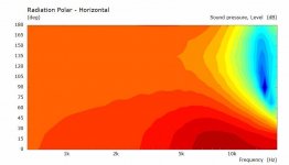
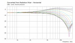
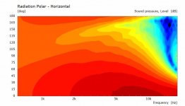
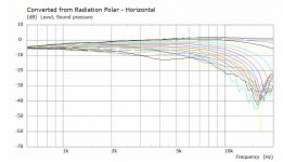
Well it didn't actually take that long 🙂
25mm driven Piston, Constant Acceleration as a base line to compare the diffraction and directivity.
300mm Tube just bigger than the driver vs sphere 104mm diameter.


25mm driven Piston, Constant Acceleration as a base line to compare the diffraction and directivity.
300mm Tube just bigger than the driver vs sphere 104mm diameter.
Attachments
ok, I have done lots and lots of testing and can see the error of my ways: listen to hifijim. He's been telling me to XO at 3000hz many times with the t25b.
What I was missing was the connection between the SD and the group delay. My first XO was all about keeping the drivers away from each other and locking down the phase. I did not know about the GD and how much it would shift. The t25b makes a 2000hz that is 0.09ms behind the 4000hz. This really mucks up the decay and turns my edge radius into a horn.
My new rule is to not push drivers past the SD. The bliesma t25b should be -6db down at 3000hz based on the SD. The eton should be -6db at 500hz. So with all that in mind, I made some new XO;s and I now like my t25b+eton setup. All I am doing is using the SD number and looking frequently at the 1/2 WL. This is the start of where time breaks.
GD/wat no baffle t25 on axis to the tweeter.


GD/water with a baffle + 44mm edge.


..
I have noticed in the REW measurements that the time was off but did not think it mattered. This is a little flawed comparison but the audax and t25b are at 1m and the rest are a little closer. The audax is the only one with eq. I also level-matched all in rew so there were not all taken at the same SPL. I wanted to see how fast a driver can make a frequency and decay. The audax ti can make a 2khz more in time than a t25b- maybe due to the grill on the t25b? The slices are all the same to show the speed of the decay.


Note how the dsm50 with an SD of 20cm2 can instantly make frequencies while the tweeters are out of time.

I started out making 2 new XO's based on an ideal sim and then made a 3rd using the second order to hear what a large spacing sounded like.
These measurements where done with the speaker with the baffle. SO= second order, FO = first order.


These were all on-axis to the tweeter. Compare that GD to my OG xo:

My focus is only on 1khz-10khz right now but the new XO based on the SD reduced the GD.
Ok, I am at the image attachment max but will post the ideal XO's later.
What I was missing was the connection between the SD and the group delay. My first XO was all about keeping the drivers away from each other and locking down the phase. I did not know about the GD and how much it would shift. The t25b makes a 2000hz that is 0.09ms behind the 4000hz. This really mucks up the decay and turns my edge radius into a horn.
My new rule is to not push drivers past the SD. The bliesma t25b should be -6db down at 3000hz based on the SD. The eton should be -6db at 500hz. So with all that in mind, I made some new XO;s and I now like my t25b+eton setup. All I am doing is using the SD number and looking frequently at the 1/2 WL. This is the start of where time breaks.
GD/wat no baffle t25 on axis to the tweeter.
GD/water with a baffle + 44mm edge.
..
I have noticed in the REW measurements that the time was off but did not think it mattered. This is a little flawed comparison but the audax and t25b are at 1m and the rest are a little closer. The audax is the only one with eq. I also level-matched all in rew so there were not all taken at the same SPL. I wanted to see how fast a driver can make a frequency and decay. The audax ti can make a 2khz more in time than a t25b- maybe due to the grill on the t25b? The slices are all the same to show the speed of the decay.
Note how the dsm50 with an SD of 20cm2 can instantly make frequencies while the tweeters are out of time.
I started out making 2 new XO's based on an ideal sim and then made a 3rd using the second order to hear what a large spacing sounded like.
These measurements where done with the speaker with the baffle. SO= second order, FO = first order.
These were all on-axis to the tweeter. Compare that GD to my OG xo:
My focus is only on 1khz-10khz right now but the new XO based on the SD reduced the GD.
Ok, I am at the image attachment max but will post the ideal XO's later.
- Home
- Loudspeakers
- Multi-Way
- Headshake's far field 3way