That is a very useful app. For a check I stuffed in some numbers from PP 25L6 amps I'd built in the mid-fifties.
I was working at IBM as an on site service tech in those daze. There were lots of 25L6 pulls from the
IBM preventative maintenance program. At the local surplus store some PTs of 170-0-170 & 25V, 0.15
secondaries were on sale, So several PP 25L6 (metal) amps got gebuilt. The test results are still here in the pile.
So B+ to the plates was 180V, the screens at 135V. All the OPTs were Hammond 125D which in those
days were at a good price. The loadline calculator app comes very close to measured results.
The 6W6 was used as sub for the 25L6, they are essentially the same tube.
Stayed at IBM only a year & half, got a job with a company doing R&D on real digital computers.
A very wise career change, for me anyway.
Attachments


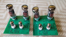
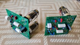
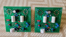
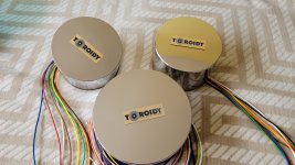
Short update. I just received the transformers from Toroidy and I finalized the PCBA's. This week I will start the testing and measurements. First I will power up the power supply and measure it and then I will power-up the amplifiers and adjust all bias currents and then I will perform some measurements. I'll keep this thread updated once I have more info. I attached some pictures of the PCBAs and of the transformers. I did not have the time to clean the KT88 tube socket solder joints 🙂 Sorry for that 🙂
Attachments

Nice! Following with interest. I am already overloaded with projects but this does look inspiring👍
A quick and short update. I managed to start testing the power supply and the power amplifier. The power supply works just fine as it is. I have the following values:
VHT= 385Vdc (no load), 360Vdc (loaded)
Vdriver= 330Vdc (no load)
Vinput= 188Vdc (no load)
Voutout_screens= 188Vdc
Then I have the lower voltages that are used for gate bias:
Voutput_bias= -20.03Vdc
Vinput_bias= -37.8Vdc
Vdriver_bias= -10.37Vdc
I then proceeded to power the power amplifier and I stared by applying the 385Vdc to the center tap of the output transformer and I adjusted the -20Vdc grid bias to get around 45mA through the output tubes. I will crank up the bias current through the output devices once everything is thoroughly tested. The rest of the amplifier (input stage and driver stage) were not powered at this stage.
I proceeded to power the input stage and the driver stage as well. Unfortunately I was running out of available time and I only got the quickly measure the bias current through the input stage (~2mA - 1mA through each half of the tube) and through the driver stage (~12mA - 6mA through each half of the tube). While powering up the complete amplifier I added an 8OHM resistor on the output winding and I ran the feedback wire back to to the input stage. I did notice some oscillation (of course there is oscillation 🙂 ) after the output stage tubes warmed up. I did not have the time to dig a bit deeper into this but I did notice that the current through the output tubes went out of balance. One had around 45mA through it and the other one had around 60mA. Nothing alarming but definitely needs looking into.
Next I will power the output stage by itself and I will set the bias and the balance again. After I will power the input stage and the driver stage with the output stage disconnected (either not powered or by disconnecting the coupling capacitors). By doing this I want to precisely set the DC bias balance through the two stages and only after this is set I will connect all three stages together.
The oscillation will most probably still be there and I will start investigating with the scope. I also realized that I forgot to add the R-C zobel network that should be on the 8OHM output (feedback trace). I will add that as well.
The tests above were all done with the output configured a pentode. I will also test with UL to see how it behaves.
The first suspect for the oscillation is the output transformer. Therefore I will add a 1nF+1K between the anode and the screens of the output devices (UL tap and the anode tap of the output transformer) and see what this dose to he oscillation.
Any suggestions are welcome 🙂
That is a very useful app. For a check I stuffed in some numbers from PP 25L6 amps I'd built in the mid-fifties.
I was working at IBM as an on site service tech in those daze. There were lots of 25L6 pulls from the
IBM preventative maintenance program. At the local surplus store some PTs of 170-0-170 & 25V, 0.15
secondaries were on sale, So several PP 25L6 (metal) amps got gebuilt. The test results are still here in the pile.
So B+ to the plates was 180V, the screens at 135V. All the OPTs were Hammond 125D which in those
days were at a good price. The loadline calculator app comes very close to measured results.
The 6W6 was used as sub for the 25L6, they are essentially the same tube.
Stayed at IBM only a year & half, got a job with a company doing R&D on real digital computers.
A very wise career change, for me anyway.
Speaking of IBM there was an IBM tube tester for sale on eBay a while ago. Got a chuckle from that.
With the help of a member from another forum (ASR) I was able to tame the oscillation. His suggestion was to remove the R-C networks connecting the input and the driver stage (33pF + 47K) and I also removed the R-C networks that I placed over each primary half of the output transformer. The later R-C networks did help but did not completely solve the oscillations. The suggestion of the said member was to add an R-C network between the plates of the input valve. I used 15nF+1k. I also stared testing open loop. The oscillations were gone and the frequency response of the amplifier can be seen below.

and the square wave response can be seen below

This seems fine and connecting the feedback should make the amplifier work just fine.
Therefore I connected the feedback and the results can be seen below (don't mind the title of the graph, it should read "closed loop gain"):

The issue here was that the HF roll-off starts way too early, having -3dB at around 1kHz. By looking at the circuit, the main suspect is the lead capacitor (the 22nF placed over the 6.8k feedback resistor). By removing this I got the following results:

This is much better. I now have -3dB at around 45kHz. The square wave response looks much better as well:
1kHz

10kHz

The conclusion is that the original frequency compensation is good but not adequate for this output transformer. I probably could have made it work but adding the R-C network between the plates of V1 is a simpler solution and it seems to work just fine. Thanks @SIY. Next I will post some THD measurements. I still had a small 50Hz oscillation that needed to be looked at.
and the square wave response can be seen below
This seems fine and connecting the feedback should make the amplifier work just fine.
Therefore I connected the feedback and the results can be seen below (don't mind the title of the graph, it should read "closed loop gain"):
The issue here was that the HF roll-off starts way too early, having -3dB at around 1kHz. By looking at the circuit, the main suspect is the lead capacitor (the 22nF placed over the 6.8k feedback resistor). By removing this I got the following results:
This is much better. I now have -3dB at around 45kHz. The square wave response looks much better as well:
1kHz
10kHz
The conclusion is that the original frequency compensation is good but not adequate for this output transformer. I probably could have made it work but adding the R-C network between the plates of V1 is a simpler solution and it seems to work just fine. Thanks @SIY. Next I will post some THD measurements. I still had a small 50Hz oscillation that needed to be looked at.
Next I used the QA401 to perform some THD and frequency response measurements.


To be honest the THD looks to be very respectable at 0.035% for 5W on 8OHM. The big issue is the 50Hz noise or oscillation. The frequency response looks really nice apart from the 50Hz.
The main suspect for this 50Hz noise/oscillation is the 6.3Vac voltage used for the filaments of the valves. I tried re-routing all the filament wires as far away as possible from all the sensitive areas. I also made sure all the wires were twisted together. This had no impact on the 50Hz noise. I then started suspecting the input tubes. I know that some tubes will leak more filament noise than others. I then used DC voltage to feed the filaments of the input tube and the driver one. BINGO! This solved the 50Hz noise issue and the results can be seen below:
1W on 8OHM

5W on 8OHM

and the frequency response:

This is looking really nice in my opinion. Really flat frequency response in the audio band and very respectable THD and THD+N figures. I can also increase the quiescent current through the output valves and the THD should get a bit better. The maximum output power is around 20W into 8OHM. I know this is not much but it is enough for my needs. Higher power can be achieved by using a higher supply voltage. The conclusion is that I will most probably use DC voltage for the heater of the input tube and the driver one. I will also look at other brands that might have a better performance. Next I will setup the second amplifier module to work in ultra linear configurating (this one is in pentode configuration) and I will measure it to see how the two configurations compare.
To be honest the THD looks to be very respectable at 0.035% for 5W on 8OHM. The big issue is the 50Hz noise or oscillation. The frequency response looks really nice apart from the 50Hz.
The main suspect for this 50Hz noise/oscillation is the 6.3Vac voltage used for the filaments of the valves. I tried re-routing all the filament wires as far away as possible from all the sensitive areas. I also made sure all the wires were twisted together. This had no impact on the 50Hz noise. I then started suspecting the input tubes. I know that some tubes will leak more filament noise than others. I then used DC voltage to feed the filaments of the input tube and the driver one. BINGO! This solved the 50Hz noise issue and the results can be seen below:
1W on 8OHM
5W on 8OHM
and the frequency response:
This is looking really nice in my opinion. Really flat frequency response in the audio band and very respectable THD and THD+N figures. I can also increase the quiescent current through the output valves and the THD should get a bit better. The maximum output power is around 20W into 8OHM. I know this is not much but it is enough for my needs. Higher power can be achieved by using a higher supply voltage. The conclusion is that I will most probably use DC voltage for the heater of the input tube and the driver one. I will also look at other brands that might have a better performance. Next I will setup the second amplifier module to work in ultra linear configurating (this one is in pentode configuration) and I will measure it to see how the two configurations compare.
Not just yet. I will put the final schematic here once I update it.You got good advise. Do you have a final schematic.
As I said earlier, the second power amplifier PCB will be setup to work in UL mode so that I can assess witch mode has better performance (UL or pentode). I managed to do this today and in order for it to work in UL mode I had to perform a few modifications.

The THD was the big surprise. It's clear that the 2nd harmonic is a lot bigger than it was in pentode mode. In pentode mode the THD was 0.017% (1W) and in ultra linear it is 0.096% at 1W. This is a big difference in my opinion. It gets even bigger at 5W, 0.038% vs 0.21%. Output power was about the same, 20W in UL mode and around 18W in pentode mode. Is this THD difference something normal? I was really expecting the THD in UL to be very similar to the THD in pentode mode but this is clearly not the case.
The conclusion is that I will modify the second module to work in pentode mode and I will use pentode mode for the final build. I will keep this thread updated with construction photos once I start.
1W output power

5W output power

- the grid voltage of the KT88 valves had to be lowered from around -18Vdc to around -40Vdc.
- the R-C compensation network that I placed on the anodes of V1 was modified to 1k + 330pF. This gave a -3dB frequency of around 40kHz
- the 100nF capacitor placed on the feedback input of V1 was increased to 200nF. This improved the LF response.
The THD was the big surprise. It's clear that the 2nd harmonic is a lot bigger than it was in pentode mode. In pentode mode the THD was 0.017% (1W) and in ultra linear it is 0.096% at 1W. This is a big difference in my opinion. It gets even bigger at 5W, 0.038% vs 0.21%. Output power was about the same, 20W in UL mode and around 18W in pentode mode. Is this THD difference something normal? I was really expecting the THD in UL to be very similar to the THD in pentode mode but this is clearly not the case.
The conclusion is that I will modify the second module to work in pentode mode and I will use pentode mode for the final build. I will keep this thread updated with construction photos once I start.
1W output power
5W output power
The UL has full HT on the screen whereas the pentode mode does not hence the change in grid voltage. The change in 2nd harmonic seem to indicate some sort of in-balance on the valve screens of OPT. The hum can also get in on the negative bias.
I will try to perform the measurements with the other OTP as well. I will have another look at the wiring to see if I didn't miss something.The UL has full HT on the screen whereas the pentode mode does not hence the change in grid voltage. The change in 2nd harmonic seem to indicate some sort of in-balance on the valve screens of OPT. The hum can also get in on the negative bias.
Same screen resistor values just to check. The UL should in theory should have the same symmetry. You could also check pentode mode with the screen at HT. This then is more like for like. For the lowish HT you are using tieing the screen to HT should give you the best output power.
I checked the setup and I discovered that I made a mistake in the GND from the output winding. I corrected this but apart from the 50Hz hum, nothing changed. I also performed the measurements with the second output transformer and again, no differences. So my conclusion is that this circuit with these transformers perform significantly better in pentode mode. Therefore I will use them in this configuration.
The IBM 604 Electronic Calculator used between 900 & 1500 6J6s, all mounted on assemblies to make a complete flip-flop.Speaking of IBM there was an IBM tube tester for sale on eBay a while ago. Got a chuckle from that.
All plug-able for quick replacement. The number of 6J6s depending on what the customer paid for in performance.
The logic was 1248 BCD. So a four function calculator that could heat a house. I/O was IBM punch cards, of course, big $$$ for IBM.
The 6J6 heater supply was by a saturable reactor driven by a 6L6. During that time all IBM equipment was leased, not for sale.
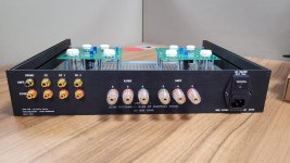
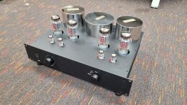
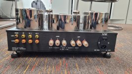
I know it is a long time since I updated this thread but this doesn't mean that I wasn't working on the project. After all the measurements done on the boards, the next step was to order an enclosure and to start fitting everything inside it. I chose an enclosure from ModuShop, the Galaxy. I tried to keep the costs as low as possible while still looking good. I already spent a big budget on the project so far so I didn't want to go overboard with the enclosure. I had some minimal customizations done on the front and back panel. I also wanted to have the top cover customized but this can only be done on aluminium covers and the cost was to high. I chose a top cover from steel and I drilled it myself. I will try to give it a paint cover before installing it.
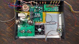
As I said in previous posts, I had to use DC for the filaments of the input and driver tubes as the 50Hz component was way to high. For this I will use a separate toroidal transformer and two separate LM317 regulators (one for each channel). Another important thing is to not leave the 6.3Vdc for the input/driver tubes floating. So the ground of the 6.3Vdc connects to the main ground of the amplifier.
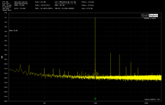
I managed to install and wire the left channel and I also performed some quick measurements to make sure everything works just fine. I am again baffled by these measurements and how good these are considering that I use tubes 🙂. Of course you get much better results from solid state amps but I have to say that these are not bad results in my opinion (0.02% THD at 1W).
I also chose to include the PHNO pre-amp inside the amp. That is the PCB in the upper right corner. Input switching will be done by relays and a rotary switch.
As per the advice I received, I also included a fan that is powered from the 6.3Vdc of the right channel. I'm not sure if this will suffice or not but I can always use a higher voltage to power it if this is needed. I really do not want this fan to be audible.
I hope to have the time to finalize all the wiring and actually listen to this things as I didn't have the chance to hear it yet 🙂
As I said in previous posts, I had to use DC for the filaments of the input and driver tubes as the 50Hz component was way to high. For this I will use a separate toroidal transformer and two separate LM317 regulators (one for each channel). Another important thing is to not leave the 6.3Vdc for the input/driver tubes floating. So the ground of the 6.3Vdc connects to the main ground of the amplifier.
I managed to install and wire the left channel and I also performed some quick measurements to make sure everything works just fine. I am again baffled by these measurements and how good these are considering that I use tubes 🙂. Of course you get much better results from solid state amps but I have to say that these are not bad results in my opinion (0.02% THD at 1W).
I also chose to include the PHNO pre-amp inside the amp. That is the PCB in the upper right corner. Input switching will be done by relays and a rotary switch.
As per the advice I received, I also included a fan that is powered from the 6.3Vdc of the right channel. I'm not sure if this will suffice or not but I can always use a higher voltage to power it if this is needed. I really do not want this fan to be audible.
I hope to have the time to finalize all the wiring and actually listen to this things as I didn't have the chance to hear it yet 🙂
Attachments
-
 8564206d-b7a6-48ed-b394-8e6fa31f0506.jpg180.5 KB · Views: 172
 -
 b2941913-a5cb-45d4-b4e9-b2c32ccd4456.jpg204.8 KB · Views: 166
 -
 6e52f5ea-5a1b-41fd-b7a4-beedf8b46f53.jpg175.7 KB · Views: 180
 -
 f3491b8a-c0e0-459b-830e-e3c2ae4361d6.jpg344.1 KB · Views: 183
 -
 tube_L_ch_assembled_gnd_to_supply+GND_on_PCB+GND_on_analyzer.png29.3 KB · Views: 179
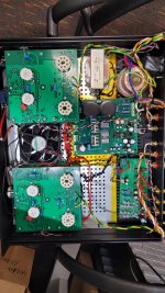
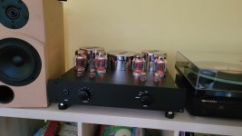
I managed to put everything together and to have a listen to it. I have to say that I really like the way it sounds. I can't say that it sounds better than a transistor amp but it's crispy clear all over the frequency band and low frequencies sound great. I guess the output transformers do a really good job.
I still have to do some more tweaking:
I still have to do some more tweaking:
- I want to implement a delay for the anode voltage so that I do not stress the tubes at start-up. The heaters will start and after 30s or 1min the anode voltage will be applied.
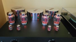
- I still have to do something about the heaters for the KT88's. Each of these require 1,6A for the heater, so in total I need 6.4A and the transformer windings provide only 2x 3A. I still have a spare 6.3Vac winding that can output 2A. So I have two options here, I either connect all three 6.3Vac windings in parallel (3A + 3A + 2A) or I wire the 2A winding to one of the KT88s. Is there a preference here? I now have the two 3A windings in parallel going to all four KT88s.
- I want to improve the internal wiring. The earth wire needs to be well fastened to the chassis. I have to wire the internal led of the power switch.
- I want to perform some temperature measurements on some of the internal components. I will be using a PicoLog TC-08 temperature logger and measure the temperature for some internal components like the smaller toroidal transformer used for auxiliary voltages and the heaters of the 12AX7 and 12AU7 tubes, the big electrolytic capacitors, the MOSFETS and the LM317/LM337 regulators. I will also look at the temperature from the PCB surface near the output tubes. Just to make sure it doesn't get too hot.
Attachments
-
 9cf267a0-7dd0-443e-8728-71992cac0f11.jpg264.8 KB · Views: 175
 -
 8bb82a15-ce40-4a8e-8672-76128f12eda2.jpg476.2 KB · Views: 164
 -
 5682a2b8-1c69-4d69-8bad-86663511e0a4.jpg377.9 KB · Views: 158
 -
 f9e49e9a-3b7b-42cc-b5a9-da115fabe722.jpg97.3 KB · Views: 150
 -
 096256c8-6b98-446a-b7f9-dd917a52d29b.jpg92.1 KB · Views: 160
Congratulations!I managed to put everything together and to have a listen to it. I have to say that I really like the way it sounds.
If you guys think there are other things I can do in order to prolong the lifetime of the output tubes, then please let me know.
- I still have to do something about the heaters for the KT88's. Each of these require 1,6A for the heater, so in total I need 6.4A and the transformer windings provide only 2x 3A. I still have a spare 6.3Vac winding that can output 2A. So I have two options here, I either connect all three 6.3Vac windings in parallel (3A + 3A + 2A) or I wire the 2A winding to one of the KT88s. Is there a preference here? I now have the two 3A windings in parallel going to all four KT88s.
 It was enjoyable looking over your shoulder as you put it all together. Great job!
Regarding heating your tubes - how are you heating the noval tubes now? As far as the KT88: As hooked up now, do you get close to 6.3 Vac across the heaters? My belief is that the ratings of a power transformer is limited by the overall heat generations in the coils and the dissipation thereof, more that the current limitation of wire in individual coils. So, I think drawing 3.2A rather than 3A from a coil should not be a problem if the whole transformer stays at acceptable temperature. If I were you I would heat each pair of KT88 with one 6.3V, 3 amp coil (as long as you get ~6.3 v) and monitor the power transformer temperature carefully until I’m convinced it stays benign.
Don't care about B+ delay. It's not needed and it might only give trouble !!
- Home
- Amplifiers
- Tubes / Valves
- KT88 amplifier