Hi,
I'm searching through the thread(s) but can't find the power up / measurement sequence for the amp 🤔
Help/link would be much appretiated.
I'm searching through the thread(s) but can't find the power up / measurement sequence for the amp 🤔
Help/link would be much appretiated.
I compiled my own little list from pieces in various threads. The whole adventure is here:
https://www.diyaudio.com/community/threads/a-noobs-first-first-watt-m2x.338175/
The startup sequence I used is:
Final Checks and DC Offset
https://www.diyaudio.com/community/threads/a-noobs-first-first-watt-m2x.338175/
The startup sequence I used is:
Final Checks and DC Offset
- Verify that the power inputs are not shorted to ground with a multi meter.
- Dim Bulb Check - Don't forget to remove the Dim Bulb tester after the check!
- Hook up V+,V-, and PS ground to channel A, turn on the power and look for smoke.
- Power off and disconnect Channel A
- Hook up V+,V-, and PS ground to channel B, turn on the power and look for smoke Power offHook up V+,V-, and PS ground to channel A,
- Initial DC Offset
- Close up chassis (temp with top lid not secured), tidy and secure wiring
- Short Inputs
- Attach DMMs to Speaker Terminals or Output and Ground O on amp boards
- Power on and rough in offset
- Finish Case and DC offset check
- Long Power up
- Allow to set for an hour or more – fine tune DC offset
- Check DC Offset after 24 hours

Many thanks! I read your thread, it's very helpful for Greenhorns like me 

My PSU is up and running (however, I will install two mains relais as recommended by ZM), so too late for the light bulb check The first power up seams to be realistic today or tomorrow, still without chassis.
My PSU is up and running (however, I will install two mains relais as recommended by ZM), so too late for the light bulb check
The first power up seams to be realistic today or tomorrow, still without chassis.Could I get a step by step on how some of you have tested the daughter boards before adding into the M2x?
I thought about building a test bench with a torroidal, diodes, and CRC filter but wondering if the below DC power supply would work if I set it to 24V. Does it have the + and - I need or do I just need V+ and ground? V+ to pin 3 and ground to pin 1 is what I saw someone do on the thread.
Do I measure anywhere or just check for smoke?
Here is the power supply I currently have.
DC Power Supply, OUBEL 60V/5A Variable Lab Bench Power Supply, Switching Regulated Power Supply with 4-Digit LED Display/Alligator Cord/US Power Cord https://a.co/d/aTiZxDO
I am mostly a risk taker, sooo
I generally just put the board under the magnifier and give it a very close inspection
Check for correct orientation and then go over the resistors with DMM - small board only takes 10 mins.
I have build all the daughter boards and they all have worked first time without an issue, YMMV!
I generally just put the board under the magnifier and give it a very close inspection
Check for correct orientation and then go over the resistors with DMM - small board only takes 10 mins.
I have build all the daughter boards and they all have worked first time without an issue, YMMV!
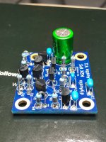
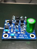
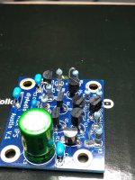
Yea. The first time I built the M2x all daughter boards worked great. The Austin is my biggest worry because of the Orientation of the transistors. The 1845s and 992s don’t have the same pinouts as the ZTX and I wanted to confirm I had them the right way. Does anyone have a closeup picture of their austin boards so I can confirm?
Hi🙂 look hereCould I get a step by step on how some of you have tested the daughter boards before adding into the M2x?
I thought about building a test bench with a torroidal, diodes, and CRC filter but wondering if the below DC power supply would work if I set it to 24V. Does it have the + and - I need or do I just need V+ and ground? V+ to pin 3 and ground to pin 1 is what I saw someone do on the thread.
Do I measure anywhere or just check for smoke?
Here is the power supply I currently have.
DC Power Supply, OUBEL 60V/5A Variable Lab Bench Power Supply, Switching Regulated Power Supply with 4-Digit LED Display/Alligator Cord/US Power Cord https://a.co/d/aTiZxDO
https://www.diyaudio.com/community/threads/the-diyaudio-first-watt-m2x.321925/page-104#post-5811555
My lack of knowledge requires a quick question. When mounting the transistors on the heatsink, do I need to electrically insulate it or is thermalgrease enough?
Perfect!! Very helpful. I looked all over for a closeup of these boards.Here three pics of my Austin board. Here's three angles, let me know if you need anything else.
Yes, electrical insulation is required. I recommend Keratherm 86/82, so no thermal paste is necessary.My lack of knowledge requires a quick question. When mounting the transistors on the heatsink, do I need to electrically insulate it or is thermalgrease enough?
Thanks mate.Yes, electrical insulation is required. I recommend Keratherm 86/82, so no thermal paste is necessary.
Could I get a step by step on how some of you have tested the daughter boards before adding into the M2x?
I thought about building a test bench with a torroidal, diodes, and CRC filter but wondering if the below DC power supply would work if I set it to 24V. Does it have the + and - I need or do I just need V+ and ground? V+ to pin 3 and ground to pin 1 is what I saw someone do on the thread.
Do I measure anywhere or just check for smoke?
Here is the power supply I currently have.
DC Power Supply, OUBEL 60V/5A Variable Lab Bench Power Supply, Switching Regulated Power Supply with 4-Digit LED Display/Alligator Cord/US Power Cord https://a.co/d/aTiZxDO
I built a input board test bench just using an extra amp-board. For PSU I used a lab-supply which is nice because of the current limiter. Then smoke can be avoided. I use RCA for in and output so I can measure using scope etc. and look at the signal....e.g. like sinus in, sinus out and square in, square out.

First power on... no smoke, no sparks no fuse blown (1,25A @230vac).
I was able to set the DC offset to 57 mV. Now I let it cook for 1 hour, let see what comes.

no fuse blown (1,25A @230vac).I was able to set the DC offset to 57 mV. Now I let it cook for 1 hour, let see what comes.
Is the Antek AS-2222 a usuable transformer for the M2x or is it too large? I know the M2x settles the voltage.
I have an extra on hand so curious.
I have an extra on hand so curious.
A pair of AS-2222 transformers would be very suitable for a dual-mono supply. One per channel
Not quite enough for a shared supply, though.
Not quite enough for a shared supply, though.
So, after 1 hour the DC offset has settled to -41mV... yes, minus... is it a problem?
If yes, should I change R6 to 37k and RV1 to 20k as described by Mark, when using the Tea Bag IC? I however the Mountain View input card.
Many thanks for any help in advance.
If yes, should I change R6 to 37k and RV1 to 20k as described by Mark, when using the Tea Bag IC? I however the Mountain View input card.
Many thanks for any help in advance.
Last edited:
Yes, it's stable at -41 mV.If just the numerical value is below 50mV you should be OK.
The 4u300 heatsink ist warm, but I can touch it for a long time.
- Home
- Amplifiers
- Pass Labs
- The diyAudio First Watt M2x