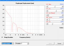
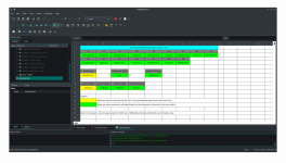
You can now see why I wanted to keep using the chart scaling factors. Otherwise the maximum value on the Y-axis in this case would have been 1800000000. Definitely more than 3 characters 🙂.Power in GIGAWATTS!!! 😆😱

It's best not to exceed 1210000000, otherwise delay increases significantly.1800000000
Actually, if there is no clipping, power compression or distortion, things like group delay and impulse response should theoretically not change, regardless of the input power level. Diaphragm displacement is another matter, however - a linear one-way displacement of 4.8 metres at 100 Hz is probably asking just a little too much of any driver 🙂.
Hello
New to HornResp and trying to get a grip on how it works. I enter S1 and s2, 4 drivers of Sd=51.9 x 4, etc, then I click TL-design. Notoriously, Hornresp then overwrites the S1 parameters to 71.31. I need to understand what is going on and why this happens (each time TL design is clicked). I cannot find a "save" of my given input so I am a bit stuck. 71.31 is also a completely wild (wrong) size, since each of the 4 drivers has Sd 51.9. I also has a problem with the speaker configuration wisard. I define 4 drivers, but a minute later the program has reverted driver configuration to one single driver. Again, how to completely stop this overeager recalculation? Thanks for some introductory remarks on this.
New to HornResp and trying to get a grip on how it works. I enter S1 and s2, 4 drivers of Sd=51.9 x 4, etc, then I click TL-design. Notoriously, Hornresp then overwrites the S1 parameters to 71.31. I need to understand what is going on and why this happens (each time TL design is clicked). I cannot find a "save" of my given input so I am a bit stuck. 71.31 is also a completely wild (wrong) size, since each of the 4 drivers has Sd 51.9. I also has a problem with the speaker configuration wisard. I define 4 drivers, but a minute later the program has reverted driver configuration to one single driver. Again, how to completely stop this overeager recalculation? Thanks for some introductory remarks on this.
Presumably with "volume velocity" being measured in barrels per day (or should that be bananas per day), rather than in the normal acoustics unit of cubic metres per second 🙂.That would be an oil well pump going bananas
I enter S1 and s2, 4 drivers of Sd=51.9 x 4, etc, then I click TL-design.
I define 4 drivers, but a minute later the program has reverted driver configuration to one single driver.
Hi Kyrre,
There is no need to enter S1 and S2 values, the TL Design optimisation tool will do that for you.
The TL Design tool is intended to be used with one driver only. If you specify multiple drivers and then use the tool, the number of drivers will be automatically set back to one.
If you want to use multiple drivers, you will have to design the TL system manually, and not use the TL Design tool.
Kind regards,
David
I can't resist it, I will have a look to see if the tool can be modified to handle multiple drivers as well 🙂.The TL Design tool is intended to be used with one driver only.
Hello David,
Regarding the import function, Hornresp need to receive a TXT file with all parameter (full list) or we can reduce some parameter to a minimal list that will still work?
Regarding the import function, Hornresp need to receive a TXT file with all parameter (full list) or we can reduce some parameter to a minimal list that will still work?
Rather than fullscreen, what about a straight doubling. Eg instead of 640x480, have 1280x960? I don't know if that would be easier to implement, maybe not... I also use 1920x1080.However if you could just enable the fullscreen button that would be a great improvement. My screen is 1920x1080 pixels
I've never really been into the magnifier because it changes other things. In any case it gave me this message, which I didn't expect since I don't use DPI settings. Maybe it's the VM?..

However if you could just enable the fullscreen button that would be a great improvement.
It wouldn't help, see Attachment 1.
Rather than fullscreen, what about a straight doubling.
It wouldn't help, see Attachment 2.
Hornresp currently has forty six forms and several hundred control objects on those forms. Each form and control object would need to have its Left, Top, Width, Height and Font Size property values changed. The schematic diagram, system model and chart graphics would also all have to be re-scaled. The task would be absolutely massive. It's not going to happen.
Attachments
Regarding the import function, Hornresp need to receive a TXT file with all parameter (full list) or we can reduce some parameter to a minimal list that will still work?
The only record files that should be imported into Hornresp are ones that have been exported from Hornresp or from a BOXPLAN spreadsheet.
The files should not manually edited by the user - in other words, the parameter list cannot be reduced.
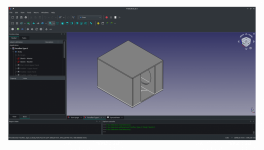
the response looks quite peaky, but if that's okay with you, why not. Lc1 is lenght of chamber 1, Lo1 is offset of driver in chamber 1.Does everything look good or there are some mistakes? And what does LC1 and Lo1 actually means?
what does LC1 and Lo1 actually means?
Lc1 is the length of chamber 1.
Lo1 is amount that the driver is offset in chamber 1.
Try adjusting the Lc1 and Lo1 sliders to see how they change the schematic diagram and the system model.
Leave the Lo1 values at zero if you don't want the driver to be offset.
EDIT - stv, you just beat me to it 🙂.
I will have a look to see if the tool can be modified to handle multiple drivers as well
It can - the feature will be added in the next update.
I know.. but whatever I do It's always like that.. I mean it's 2x21" subwoofer with 5kw rms rating each.. thats probably a reason? (just my opinion)the response looks quite peaky, but if that's okay with you, why not. Lc1 is lenght of chamber 1, Lo1 is offset of driver in chamber 1.
Hmm would that mean that in this case below lc1 and lc2 is 135cm? and driver offset at zero? 😅Lc1 is the length of chamber 1.
Lo1 is amount that the driver is offset in chamber 1.
Try adjusting the Lc1 and Lo1 sliders to see how they change the schematic diagram and the system model.
Leave the Lo1 values at zero if you don't want the driver to be offset.
EDIT - stv, you just beat me to it 🙂.
The only record files that should be imported into Hornresp are ones that have been exported from Hornresp or from a BOXPLAN spreadsheet.
The files should not manually edited by the user - in other words, the parameter list cannot be reduced.
Hi David, yes, Brian Steele create a Macro in the BOXPLAN excel files to export data for hornresp, It's very friendly but we miss the CAD interaction needs in some cases like to better evaluate the space or panels cutting. I'm doing the same but using CAD software, trying to find a friendly feeling too, I asked Brian Steele if he has interest on it but he didn't answer yet. Based on your answer I assume that the format must be precisely equals to what hornresp export do.
It would be very welcome if you could test it.
CAD software will present two difficult level
easy - You can change the sketch values and go the built-in spreadsheet to get Hornresp simulation data. See attachment
Medium - Unfortunately the CAD file does not carry the macro itself, we need to download a separate file to incorporate in the program but it increases a lot the automation during simulation.
Attachments
The more I learn hornresp, I realize how little I actually know.. 😢
The one more thing I dont understand is Wattage test with dual voice coil drivers.
Example:
Driver specifications:
21"
DVC 1 ohm
Re 0.7+0.7
BL 22.70
5000W Rms
So two dual voice coil subwoofers wired to Paralel-Series resulting 0.7ohm load on amplifier. How can I simulate this in hornresp?
The one more thing I dont understand is Wattage test with dual voice coil drivers.
Example:
Driver specifications:
21"
DVC 1 ohm
Re 0.7+0.7
BL 22.70
5000W Rms
So two dual voice coil subwoofers wired to Paralel-Series resulting 0.7ohm load on amplifier. How can I simulate this in hornresp?
would that mean that in this case below lc1 and lc2 is 135cm? and driver offset at zero? 😅
The driver offset is zero. Because of the nature of the enclosure layout is difficult to specify Lc1 and Lc2 as exact accurate lengths. Thankfully it doesn't matter too much - try changing the Lc1 and Lc2 values to see how the response alters. If you click on the Lc1 and Lc2 sliders, the red line that appears on the system model acoustic circuit diagram shows what the simulation model is assuming are the lengths.
- Home
- Loudspeakers
- Subwoofers
- Hornresp