

There is a refron here that say: "El que sabe, sabe" (who knows, knows). The new detector transformer is clearly very superior as the previous one. The local christian tx is now much better listened. Keep in mind that still the rf amplifier is not performing as well I dream and the IF trafos are peacked at 12MHz but no adjusted their coupling.
I'm refering to Seeley, to whichever his spirit be, my thanks to him and his colleagues.
Feeling very happy again.
I'm refering to Seeley, to whichever his spirit be, my thanks to him and his colleagues.
Feeling very happy again.
This is a partial list of my readings that helped me in this project. It will be completed when l finish the set, because as is obvious, during the progress of the design, l shall need more datum.
Patents:
US 2121103 by S. W. Seeley.
US 2561059 by M. S. Corrington.
US 2750450 by J. C. Achembach.
US 2881265 by P. C. Swierczak.
US 2892080 by D. M. Chauvin.
US 3386042 by E. J. Moes.
Articles:
K. R. Sturley "Phase Discriminator, Its Use as Frequency-Amplitude Converter for
F.M. Receception"; Wireless Engineering February 1944.
F. B. Llewelyn "Constant Frequency Oscillators"; Proceedings IRE December 1931.
C. E. Kilgour and J. M. Glessner "Diode Detection Analysis"; Proceedings IRE July 1933.
Charles Travis "Automatic Frequency Control"; Proceedings IRE October 1935.
D. E. Forter and S. W. Seeley "Automatic Tuning, Simplified Circuits and Design Practice". Proceedings IRE March 1937.
E. W. Herold "Superheterodyne Converter System Considerations in TV Receivers RCA Review 1939.
C. A. Hulberg "Neutralization of Screen-Grid Tubes to Improve the Stability of Intermediate-Frequency Amplifiers"; Proceedings IRE December 1943.
D. Maurice & J. H. Slaughter "F. M. Reception" Wireless World March 1948.
E. C. Freeland "FM Receiver Design Problems"; Electronics January 1949.
B. D. Loughlin "Performance Characteristics of FM Detector Systems" Tele Tech January 1949.
Books:
F. Langford-Smith "Radio Designer's Hanbook" 1999 edition.
F. E. Terman "Radio Engineering" ed 1937.
S. Seely "Electron-Tube Circuits" ed 1950.
Several readings sourge as a consequence of the literature attached to those books. Most of them are freely available at patents.google.com and worldradiohistory.com . Books are in my library from original copies.
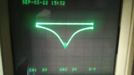
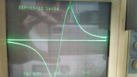
Some minutes ago l adjusted the coupling between coils at the phase discriminator transformer. Here is the result. First, the primary resonance using the 12MHz crystal as marker. The oscillo tip is at the junction of load resistors R17 and R18 where most of the AM signal is developed. In the following order, reading the FM signal at the top of loading resistors (R17) with a 100K and 430pF low pass filter to reject residual RF that makes the trace unfocused and in some instances let the IF start oscillating because of radiation of IF from cables and oscillo. The peaks are aproximatelly +/- 120KHz above and below 12MHz center frequecy for a BW of 240KHz (I listen opinions regarding if it is OK or insufficient for stereo signal). A DC shift whose cause isn't clearly determined when peaking the lesser one but my suspicion is that it corresponds to maximum conduction of upper diode in the detector. The gen signal is applied to last IF grid loading the secondary of the transformer T3 with 47R which also terminates gen cable impedance.
Now the audio output is strong compared to previous listening although some stations sound distorted; mainly those who don't came the limiter into action.
Opinions and suggestions welcome.
Now the audio output is strong compared to previous listening although some stations sound distorted; mainly those who don't came the limiter into action.
Opinions and suggestions welcome.
Attachments
Last edited:
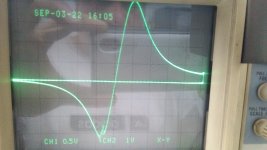
You need 312KHz for stereo. I'm not clear what the second and third picture mean exactly, or at least why there are two, but the third picture shows an off-centre alignment. You should have 0VDC at the sound take-off point, and the top and bottom of the curve should be equal height, and the curve should cross zero at the marker. The centre part of the S curve is better now but it still isn't straight. Linearity here corresponds to linearity of the audio.
We need a current schematic to discuss further.
We need a current schematic to discuss further.
Second pic shows the 12.12MHz marker at top of waveform and third the same at 11.88MHz. Remark that it is the detector tranfer only, all 3 previous stages were deactivated and inoperative during the adjustement. Tomorrow perhaps l shall make the adjustements at those 3 steps.
A full version of the squematic can be found at post #305 already posted.
A full version of the squematic can be found at post #305 already posted.
In a situation where every broadcaster would behave conform regulations (bandwidth, stability, power), 240 KHz for the discriminator would be enough. But AFAIK that situation nowadays could be called "ideal" because there are too many violations. So for a receiver with 1 bandwidth, a compromise has to be made. 350 KHz will sound great but it limits the amount of stations that can be received. Conforming to 200 KHz channel spacing only works when a majority of the most interesting stations follows the regulations.
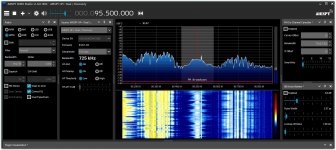
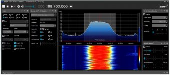
The pics show some examples for the border region Costa Rica - Panama: S1) commercial (blaring, using compressor), S2) cultural (so weak, no compressor, needs only 150 KHz). S3) religious (using compressor too), BTW the pics also show good examples of multipath.
The pics show some examples for the border region Costa Rica - Panama: S1) commercial (blaring, using compressor), S2) cultural (so weak, no compressor, needs only 150 KHz). S3) religious (using compressor too), BTW the pics also show good examples of multipath.
Attachments
You are confusing maximum deviation with required IF bandwidth, or in other words what goes into the transmitter as opposed to what comes out of it in the form of sidebands. A look at the Bessel functions and the 53KHz audio bandwidth show that you need 312KHz for maximum stereo. This is often given as 240KHz but that is based on a mistake, ignoring the interleavng effect. Most modern tuners are using 400KHz at the discriminator. HH Scott used 1MHz. You will certainly want to have optional higher selectivity in the IF strip, but not at the discriminator.
Your first picture shows transmission beyond 300KHz. Second one looks like mono.
Your first picture shows transmission beyond 300KHz. Second one looks like mono.
I only look at the bandwidth of the signal "as is being received". Somehow that has to be processed by the RX's IF section. The pics are showing wide variations, requiring up to 350 KHz bandwidth irrespective stereo and problematic with 200 KHz channel spacing. Linearity of the demodulator is a different issue.
Theoretically you need infinite bandwidth to pass all Bessel sidebands unscatched, according to Carson's rule, two times the peak deviation plus two times the maximum modulation frequency will do. That's 256 kHz at 75 kHz peak deviation and 53 kHz highest modulation frequency.A look at the Bessel functions and the 53KHz audio bandwidth show that you need 312KHz for maximum stereo. This is often given as 240KHz but that is based on a mistake, ignoring the interleavng effect. Most modern tuners are using 400KHz at the discriminator. HH Scott used 1MHz.
Why 312 kHz?
Max deviation is 67.5KHz if you leave room for SCA.
Max frequency is 53KHz.
All of this is available for both the L-R and the L+R information, by the interleaving effect.
For an audio signal of 15KHz the L-R consists of a 23KHz and a 53KHz sideband.
Half of the maximum deviation goes into the 53KHz sideband and half into the 23KHz sideband.
Modulation index for the 53KHz sideband is therefore 33.75/53=0.64.
This is three sidebands to the 1% level.
This is 312Khz. If you forget about SCA maybe you can use the whole 75KHz, which makes this more.
Most of this is from Cook & Liff p266, but they forgot the interleaving effect.
Thank you to both guys. Interesting learnings this sunny morning. Supposing good stereo reception but no SCA, which BW suggest for detector and IF stages? I believe no such signal here. And although it would be the case, sincerely I dislike it: the only time l listen one of them; it was too hissing and low trebbles with overall poor quality.
Starting to think in the decoder. First: IC or semiconductors are definitively discarded. So no kind of PLL. This leaves the classic approaches for synced 38KHz oscillator and doublers from the 19KHz pilot. Which are better?.
Please guys, remember I am learning on the way. I am an experimenter with limited resources, instrumental, tubes stock and time availability. Thus, my apologies for the questions and doubts from me. I have experience in tubes and sand, but this is the first time l start such a complex project.
Finally, may I simulate stereo signals with a PC with SB16 soundcard to adjust the decoder?
Last edited:
I have yet to detect SCA in Latin American FM spectrums - AFAIK not used here. What gets you close to the observed bandwidth and the observed loudness by listeners is applying Carson's rule for m=7.Max deviation is 67.5KHz if you leave room for SCA.
Max frequency is 53KHz.
All of this is available for both the L-R and the L+R information, by the interleaving effect.
For an audio signal of 15KHz the L-R consists of a 23KHz and a 53KHz sideband.
Half of the maximum deviation goes into the 53KHz sideband and half into the 23KHz sideband.
Modulation index for the 53KHz sideband is therefore 33.75/53=0.64.
This is three sidebands to the 1% level.
This is 312Khz. If you forget about SCA maybe you can use the whole 75KHz, which makes this more.
Most of this is from Cook & Liff p266, but they forgot the interleaving effect.
You need 6.75 kHz +/- 0.75 kHz for the pilot tone, so without RDS or SCA, you have 68.25 kHz left for the normal audio.
There was some time during 80's or 90's that LRA Radio Nacional transmited a SCA called Muzac. Rapidly dissapeared. I remeber had built a receiver using horizontal coils and a 3N128 FET circuit from a local magazine Radio Práctica or the like, disappeared too. It used the two coils from Synchroguide system, one as input tuned circuit (the taped one) and the single wound as detector. The original circuit used positive grounding and a 9V battery, I reversed the circuit to negative ground and put into my father's build AM/FM tuner. But, again, unpleasant listening.I have yet to detect SCA in Latin American FM spectrums - AFAIK not used here. What gets you close to the observed bandwidth and the observed loudness by listeners is applying Carson's rule for m=7.
No wonder Muzac ( = background music for malls) disappeared. FM only works great for mono. The use of subsystems on the carrier implies (much) noise. That effect shows very well even on simulations: co-channel interference is quite a high frequency mess, fairly well suppressed by de-emphasis network but affecting stereo and higher sidebands (>53 KHz). Semi-official stations (legalized pirates) make the situation worse by using m=7 or higher and spilling over in adjacent channels.
I don't know exactly if muzac dissapear everywhere around the world. It dis here. One day simply wasn't on air no more. Then I disassemble the receiver and saved the coils.
Surely not! Muzac, aka elevator music, appears to be ubiquituous, at least here in Gemany. Have a look at the charts and what's common in the mass market, and you'l see what I mean 🤢 🤮!
🤮!
Best regards!
🤮!Best regards!
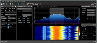
On the SDR spectrum, during pause of the program using the baseband, all subchannels clearly show. Some stations here are using RDS but none are using SCA. Which is the main advantage of those software radios: from instable carrier to modulation index, spurious emissions, subcarriers etc. everything shows up in the spectrum to the extent that legally valid complaints can be filed in case of violating laws re broadcasting.I don't know exactly if muzac dissapear everywhere around the world. It dis here. One day simply wasn't on air no more. Then I disassemble the receiver and saved the coils.
- Home
- Source & Line
- Analogue Source
- A new FM tuner with Compactron Tubes