Yes, this is a serious disadvantage of the transimpedance amplifier, and the reason why it has not become popular. This drawback can be eliminated only by providing the user with an easy calibration method, preferably automatic. It is possible separately for each channel. I'm even thinking of using a microcontroller for this.Sadly, not only that we by no means can do without measurements for each specific cartridge in order to compensate for the L\R tau
In this regard, the "Puffin phono dsp" project is very interesting (manual). This is truly the phono stage of the XXI century! But its body and display looks very scary, like a thousand devils. I do not want to use the digital domain, but a lot can be done in analog form, and the microcontroller is used only for control.
I tried to do that using PIB and set of cpacitors, but "aperiodic" from Suhov anyway betterThis drawback can be eliminated only by providing the user with an easy calibration method, preferably automatic. It is possible separately for each channel. I'm even thinking of using a microcontroller for this.
There is not circuit and firmware info, so its only marketing image with no practical value.In this regard, the "Puffin phono dsp" project is very interesting (manual).
The main thing is a set of functions, and implementing them is not a problem. In an amplifier that already has a processor that can do calibration, a transimpedance amplifier is a good fit. There are interesting facts on the developer's Facebook, for example, how high-frequency correction helps to equalize the frequency response of cartridges.There is not circuit and firmware info, so its only marketing image with no practical value.
Agree with you that all of us must know Ohm`s law and other (also mathematics) fundamentals, but the final circuit imho must be verified and optimized using modern simulator.Everyone can do whatever they like as long as it is legal, of course, but for me personally, calculating transfer functions and manipulating polynomials is one of the fun parts of the hobby. Sitting behind a simulator is not, I do more of that than I like at work.
Verification by simulation is pretty much mandatory for integrated circuit design; breadboards are not practical anymore, and test chips are expensive and have only limited options for debugging. I don't see why a hobby circuit on a PCB or perfboard must be simulated, though: you can change values, solder extra components, access any node... It can be simulated if you like to, of course.
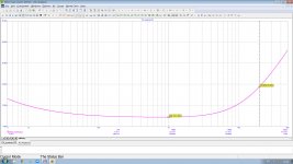
LeonivBy changing the time constant of 3180 µs, the frequency response hump caused by the DC servo can be eliminated. But the calculation becomes confusing, it is impossible to change something in the integrator without changing the RIAA correction circuits. Probably, filtering rumble and warping is better done in a separate circuit.
where are you injecting the subsonic filter/DC servo correction signal?
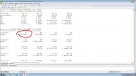
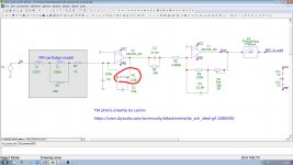
I will now give an example why I consider simulation more important than calculation. For several weeks we have been discussing the advantages and disadvantages of Leoniv's TIA-phono stage, but for some reason no one of "calculators" 😏 saw the main disadvantage of such a configuration. While the simulation of noise in the Microcap literally in a minute made it possible to establish 🤔 that the main source of noise in the TIA-configuration is ... resistor R1 😳. For more details, see the screenshots here (you can also download the schematic file that I typed and simulated in just a minute, as well as ANO test file, where you can find data on the contribution of each circuit element to the overall output noise) - https://www.patreon.com/posts/71458482I don't see why a hobby circuit on a PCB or perfboard must be simulated, though: you can change values, solder extra components, access any node... It can be simulated if you like to, of course.
Attachments
I can see by inspection it is only 1 dB worse than your 150 kohm termination resistor, 10 dB log10(150 kohm/120 kohm) to be precise.
Use the Norton equivalent of the noisy feedback resistor, split the current source in two equal but opposite current sources to ground, realize that the one at the output doesn't do any harm and you have shown that the feedback resistor has the same noise impact as a resistor shunted across the input.
I also see that the conductance (1/effective parallel resistance) of your cartridge model tends to zero with increasing frequency. That's different from Richard's measurements and explains why cartridge thermal noise doesn't dominate at high frequencies.
Last edited:

Regarding DC bias loops around RIAA amplifiers used as subsonic filters: one way to ensure that the DC loop does not shift the RIAA correction poles, is to put a zero in the DC feedback path right on top of each of them. That is, put an inverse RIAA network in the DC feedback loop. You can then change the DC loop bandwidth without having to correct the RIAA correction network.
Didn't know last Thursday happened a few weeks ago...The time in Ukraine must be passing really hard...For several weeks we have been discussing the advantages and disadvantages of Leoniv's TIA-phono stage...
He might have chosen your 150k value, but the next stage would probably run into clipping without adjustments...I wonder why he didn't go with one single stage doing the whole thing.At 4.7Mohm feedback the SNR would have been the GOAT and ad745 looks like a pretty potent chip.
That chip is a lot of dope...I wouldn't spare its capabilities for the money .
For the version on the op amp, I cover the DC servo only in the second stage, since the zero offset of the first stage is insignificant. Not sure if this is a good solution. In the presence of infra-low-frequency signals, their level at the output of the first stage can be large, and the integrator also requires a large output voltage to compensate for them. What can lead to an overload of the integrator.Leoniv
where are you injecting the subsonic filter/DC servo correction signal?
Resistor R1 contributes exactly the same amount of noise as the input resistor in a conventional amplifier. Here, this resistor can be made more than 120 kOhm, the only limiting factor is the overload capacity of the first stage. But so far I haven't done circuit optimization.the main source of noise in the TIA-configuration is ... resistor R1 😳.
Yes, it works.one way to ensure that the DC loop does not shift the RIAA correction poles, is to put a zero in the DC feedback path
Attachments
Then what's the point of using transimpedance preamp here? Do I miss something?Resistor R1 contributes exactly the same amount of noise as the input resistor in a conventional amplifier.
In a transimpedance amplifier, this resistor can be increased, this will not cause a change in the frequency response, since the resonance is damped. In conventional amplifiers, the increase in this resistor was achieved using a special circuit, the so-called "virtual cooling". This is not required here.
AFAIK virtual cooling is increasing input resistor's value by bootstrapping? I have difficulties to see why the input resistor attracts so much attention. It is shunted by cartridge's low impedance so the thermal noise generated by it is largely attenuated. Only at HF cart's Z becomes comparable to Rin. But the recorded signal is much higher in HF range (RIAA curve).
I did some calculations on that that were published in 2003, see the attachments of post #58, https://www.diyaudio.com/community/...ge-85-dba-sn-ratio.387375/page-3#post-7054466
When you look at the RIAA- and A-weighted total noise, the 47 kohm termination is usually the biggest noise source in the amplifier. The cartridge thermal noise is of the same order of magnitude.
When there is a record playing, record surface noise is usually far greater, but according to Nick it doesn't mask the cartridge and amplifier noise because of its different spectral distribution.
Last edited:
By the way, EW+WW drew one half of the gain switch in Fig. 5 in the wrong position and I mixed up spectral density and power spectral density.
Equation (2) doesn't seem right to me. It doesn't take 47k resistor into acount. What if we replace 47k with link? Current noise should become zero. But (2) doesn't reflect this.Better format -
Last edited:
You are partly correct, partly misinterpreting what S(inoise) in Fig. 1 stands for.
The noise sources vnoise and inoise represent the noise of the entire RIAA amplifier, including the termination resistor if there is one. As the termination resistor shunts the signal path, it contributes a term 4kT/Rterm to S(inoise), where Rterm is the termination resistance.
When you let Rterm approach zero, its noise current contribution goes to infinity. When you don't let it approach zero but make it some ridiculously small positive value, say 0.001 Ω, you will need to increase the amplifier's gain and change its correction to ensure you still have the correct transfer from the cartridge's Thévenin voltage (EMF) to the output. It isn't difficult to imagine that that will increase rather than decrease the noise floor.
One approximation I made in Fig. 1 is the assumption that the intended transfer from the cartridge's Thévenin voltage (EMF) to the RIAA amplifier output is given by the RIAA transfer. You could argue that to be exact, H(s) should represent the voltage division between the cartridge impedance and its recommended load, RIAA-weighting and A-weighting instead of only RIAA-weighting and A-weighting. The loading usually only has a substantial impact above 10 kHz or so, which is a frequency range that gets attenuated by both the RIAA- and the A-weighting, and I only needed a ballpark figure for the effective cartridge impedance, so I assumed my approximation to be good enough.
- Home
- Vendor's Bazaar
- Nick Sukhov SU-XXI MM Phono stage -85 dBA SN ratio...