Earlier I talked about the non-linearity being constant, as you'd consider with regard to amps, speakers and many things. If you try reconstructing using non harmonically related signals, the linearity (would have to) varies.
View attachment 1084765
I don't just think about electronics myself. Such transfer functions are applicable in all models of modern physics, including electronics.
On my oral exit exam, to get my BS diploma, my professor mentioned that if the world was not linear, ie: harmonic, we would have very different physics. It took my a while to fully catch what he meant, but he was right.
That's why computers and numerical analysis has become so useful nowadays, we can solve problems that have no clean solutions, only numerical solutions based on calculations. Imagine modeling a non linear transfer function... it becomes extremely difficult to do and some, like the multi body problem, can not be solved any other way.
Resonance is a phenomenon generally associated with linear differential equations. It can occur in nonlinear systems too, but the point is that it is a feature of linear systems ... that don't have any harmonic distortion by virtue of being linear
Harmonic distortion only exists in nonlinear systems, and doesn't necessarily have anything to do with differential equations
The Dunning-Kruger effect runs strong in this thread
No need to insult people.
The thread is about using "layman's language". Sorry if I used the laymen's interpretation of resonance.
I honestly didn't expect The Spanish Inquisition!

They hired the wrong person who did not know about Fourier analysis. If you did not know about transfer function of amplifier, I understand because you are not EE as you said. You can also learn about Laplace function.
Jesus man. I suggest you learn civility.
I know what you're getting at, but the sum of the 1 kHz and 2.6 kHz sines is periodic at 200 Hz, the sum of only the fifth and thirteenth harmonics, with the amplitudes of the 200 Hz fundamental along with all other harmonics being zeroEarlier I talked about the non-linearity being constant, as you'd consider with regard to amps, speakers and many things. If you try reconstructing using non harmonically related signals, the linearity (would have to) varies.
For a memoryless system (think amplifier that is much faster than any signals of interest) (transfer function is simply y = f(x) with no calculus necessary for the system description) driven by a single sine wave it is straightforward to derive the amplitudes of all the harmonics in the output from the Taylor series of the transfer function. And similarly straightforward to derive amplitudes of intermodulation products for signals that are sums of multiple sines.
For a not memoryless but time-invariant dynamic system, (system requires integrodifferential equations for a time domain representation) (think amplifier whose frequency response is nontrivial with respect to the frequencies of the input and associated harmonics of interest) there is an analog of the Taylor series called Volterra series which is very tedious to derive but enables a similar but perhaps not so straightforward calculation of distortion parameters
Bob Meyer (co author of the quintessential textbook on analog integrated circuit design) spent a fair amount of class time in an rfic design class at uc berkeley on deriving Volterra series for the transfer functions of basic transistor amplifiers. I have a paper copy of the wonderful lecture notes of this class. No idea if available on line ... but I am in awe of the efficiency with which he did all the tedious algebra, so I consider the lecture notes a record of intellectual athleticism and thus valuable in their own right, despite the unlikelihood that anyone would ever go through this process when circuit simulators will give the results needed for design purposes. I should probably review the notes to remember if any insight into amplifier design comes out from these calculations, but even if not I love that he did it.
I think in terms of "functions" as a transfer between coordinates.
Quantum is not far different - the usual thing is to represent the transforms as matrices. One such transform is the QFFT which is essentially a phase correlation between the input and one or more points around the Bloch sphere as a way to read a closest digital representation of the probability.
"not memoryless but time-invariant dynamic system"... would that be like an amplifier that has different output frequency response for different input frequencies? A frequency domain filter being applied differently depending on the frequency of the input signal?I know what you're getting at, but the sum of the 1 kHz and 2.6 kHz sines is periodic at 200 Hz, the sum of only the fifth and thirteenth harmonics, with the amplitudes of the 200 Hz fundamental along with all other harmonics being zero
For a memoryless system (think amplifier that is much faster than any signals of interest) (transfer function is simply y = f(x) with no calculus necessary for the system description) driven by a single sine wave it is straightforward to derive the amplitudes of all the harmonics in the output from the Taylor series of the transfer function. And similarly straightforward to derive amplitudes of intermodulation products for signals that are sums of multiple sines.
For a not memoryless but time-invariant dynamic system, (system requires integrodifferential equations for a time domain representation) (think amplifier whose frequency response is nontrivial with respect to the frequencies of the input and associated harmonics of interest) there is an analog of the Taylor series called Volterra series which is very tedious to derive but enables a similar but perhaps not so straightforward calculation of distortion parameters
Bob Meyer (co author of the quintessential textbook on analog integrated circuit design) spent a fair amount of class time in an rfic design class at uc berkeley on deriving Volterra series for the transfer functions of basic transistor amplifiers. I have a paper copy of the wonderful lecture notes of this class. No idea if available on line ... but I am in awe of the efficiency with which he did all the tedious algebra, so I consider the lecture notes a record of intellectual athleticism and thus valuable in their own right, despite the unlikelihood that anyone would ever go through this process when circuit simulators will give the results needed for design purposes. I should probably review the notes to remember if any insight into amplifier design comes out from these calculations, but even if not I love that he did it.
Would a filter do such a thing? Like AC coupling?
Mathematicians really don't know, they actually don't care, about physical models at all.
;^)
dave
Clearly we are in the middle of a Falling Empire era.
Part of the associated decadence is gratuitous destruction of the (good) elements which helped it rise; in this case , Science.
So we witness more and more people who, being unable to advance, take pride in wasting time, brains, resources, into useless silliness and to boot, defending it to death, applying fallacies, nonsense, and plain idiocy, which now achieves a revered status.
In our own little Audio world, we are witnessing that too, including this very thread, where incredibly anti scientific arguments are being used.
Not only showing Ignorance, but reveling in it.
Oh Brave New World.
Hello Tony,
This is sort of what I was asking earlier, I think it's been answered, especially after Jan's answer to me farther on. The curve in the transfer function changes the shape of the sine wave symetrically which results in only whole integal harmonics. I think that sums it up?
Cheers
No, Jan's answer did not answer my question.
Doing an FFT is an mathematical model to analyze the signal, but it doesn't mean that at it fundamental behavior that is HOW THE SIGNAL really is. We apply FFT analysis to "work" with a signal.
It's like this.... I can translate from English to French, generally in two ways: "machine" and "idiomatic". The machine translation, the FFT analysis, gives me an idea of what was said, but the idiomatic translation tells me exactly what was said.
Nature is full of wonderful unique circumstances.... such as the natural logarithm, Plank's Constant, yet, to address such, we tend to create a constant or a process and sweep under the rug the philosophical reason of why such constants have to exist.
BT, I think early on Jan claimed he was going to ignore me, whatever... so pretty much I've given up on discussing his claims with him.
If it changes symmetrically, that's odd order harmonics (3, 5, 7 etc). For instance, if you get closer to clipping, the peaks are rounded and that shows up as odd harmonics. This is often what you see in push-pull amps.Hello Tony,
This is sort of what I was asking earlier, I think it's been answered, especially after Jan's answer to me farther on. The curve in the transfer function changes the shape of the sine wave symetrically which results in only whole integal harmonics. I think that sums it up?
Cheers
If the distortion is assymetric, like a change in the waveform at zero crossing that is different at the rising edge from the falling edge, that's even harmonics (2nd, 4th, etc), typical for single ended amplifiers.
Jan
No, no, no! Come on Jan... clearly these effects to the waveform that you mentioned are caused by "resonance gremlins" that dwell like little parasites within the host component. Harmonic distortion results from their resonance-like behaviors. No one has actually observed a gremlin but, hey, these little bastards are tricky! The ultimate "ghost in the machine" I suppose, eh? How can you argue with "proof" like that???If it changes symmetrically, that's odd order harmonics (3, 5, 7 etc). For instance, if you get closer to clipping, the peaks are rounded and that shows up as odd harmonics. This is often what you see in push-pull amps.
If the distortion is assymetric, like a change in the waveform at zero crossing that is different at the rising edge from the falling edge, that's even harmonics (2nd, 4th, etc), typical for single ended amplifiers.
Jan
The curve in the transfer function changes the shape of the sine wave symetrically which results in only whole integal harmonics. I think that sums it up?
No, the basic fact that the waveform is repetitive with a fundamental frequency is the cause
of only integral harmonics of that frequency being present. See Fourier analysis.
The details of the waveform shape determine the individual amplitudes of the integral harmonics.
As far as the fundamental constants of physics are concerned: only constants that are dimensionless numbers
have physical meaning and importance.
Constants that have dimensions associated with them serve merely as unit conversions, peculiar to a particular system
of units. Their numerical values are of no physical significance whatsoever. Such constants may always be set equal
to unity by proper choice of the system of units.
For example, the numerical value of the speed of light, being ~3E8 m/s, has no fundamental significance, since it has units.
The fine structure constant, being ~1/137, with no associated units, does have fundamental significance.
Last edited:
I don't think so. If the part above the zero line is the mirror image of what is below, that is symmetrically around zero. The two wave parts are identical. In the example of rounded peaks, they are both rounded identically. That's odd harmonics.Hello Jan,
Yes, sorry, I probably used the wrong term. When I said symmetrical I really meant the same, or mirror image, above and below the zero crossing, I think that's right?
Cheers
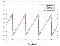
Look at an extreme case of a square wave. That's really a sinewave with lots (in theory, infinite) odd harmonics added. The more you add, the more it converges to a square - but you must add the harmonics with a very specific level that decreases with order. But it's all very symmetric.
Now take a very asymmetric wave - a sawtooth. Can't get much more asymmetric. And, you build a sawtooth by taking a sine wave and adding lots (in theory, infinite) even harmonics at a specific level and phase.
Jan
Attachments

Last edited:
Physics . . . Hmm.
I seem to remember one of our many college engineering/physicist lab experiments (all the other students took the easier non-engineering/non-physicist classes).
The experiment was about Hook's constant.
It used a spring and a mass.
The mass was pulled down (not very far, so that it would not permanently deform the spring).
Then the mass was released.
The mass and spring began to bounce (Viola! . . . Resonance, Resonance at one and only one frequency).
My goodness, a woofer in free air seems to quite closely duplicate that.
Of course, there are several more other problems with the woofer that are separate from the very well controlled Hooks constant rule.
But in both cases we have Resonance.
Consider a poorly designed single ended no negative feedback pentode amplifier has a very large capacitance wired across the output transformer primary (putting that large capacitance across the primary was what made the amplifier 'poorly designed').
The secondary is loaded by a loudspeaker that has many times higher impedance than the secondary's rated tap impedance.
What do we have? . . . We have Resonance. Resonant frequency = 1/(2 x pi x (root of L x C)).
The Resonance is at One Frequency. That resonance is not harmonic distortion (even though the non feedback single ended pentode output stage does have Lots of 2nd harmonic distortion).
Suppose the resonance is at 200Hz.
Suppose a 70Hz tone is applied to the amplifier.
At the amplifier output we get 70Hz fundamental, and 140Hz 2nd harmonic distortion.
There is No 200Hz output from the amplifier, because there is no 200Hz signal in, so the Resonance is Not Activated.
Does that make the principle of resonance and principle of distortion clear, and completely separate;
or are all the answers distorted (pun intended)?
Last edited:
The Resonance is at One Frequency. That resonance is not harmonic distortion (even though the non feedback single ended pentode output stage does have Lots of 2nd harmonic distortion).
And if the input frequency changes, the resonance still remains at the same frequency (being a property of the system).
Hello Tony,
Yes, I understand the FFT is a model but the fact that the distorted waveform can be reproduced by adding the same frequencies at the same levels shows it's an accurate one surely?
Cheers
I find it an interesting observation for sure.
Yet, I keep asking, why is this so?
The universe seems to be TOO ordered.
The universe seems to be TOO ordered.
There definitely seems to be anti-entropy out there.
On the too ordered it made me think of the wonderful world of the Fibonachi sequence and the equivalency to the golden mean.
dave
While all harmonics change, being a direct consequence of the signal involved, not the System.And if the input frequency changes, the resonance still remains at the same frequency (being a property of the system).
Proof those are 2 concepts completely unrelated, not sure why people supposedly educated try to say both are one and the same.
Can´t blame it on ignorance, so next possibility is malice.
Physics . . . Hmm.
I seem to remember one of our many college engineering/physicist lab experiments (all the other students took the easier non-engineering/non-physicist classes).
The experiment was about Hook's constant.
It used a spring and a mass.
The mass was pulled down (not very far, so that it would not permanently deform the spring).
Then the mass was released.
The mass and spring began to bounce (Viola! . . . Resonance, Resonance at one and only one frequency).
My goodness, a woofer in free air seems to quite closely duplicate that.
Of course, there are several more other problems with the woofer that are separate from the very well controlled Hooks constant rule.
But in both cases we have Resonance.
Consider a poorly designed single ended no negative feedback pentode amplifier has a very large capacitance wired across the output transformer primary (putting that large capacitance across the primary was what made the amplifier 'poorly designed').
The secondary is loaded by a loudspeaker that has many times higher impedance than the secondary's rated tap impedance.
What do we have? . . . We have Resonance. Resonant frequency = 1/(2 x pi x (root of L x C)).
The Resonance is at One Frequency. That resonance is not harmonic distortion (even though the non feedback single ended pentode output stage does have Lots of 2nd harmonic distortion).
Suppose the resonance is at 200Hz.
Suppose a 70Hz tone is applied to the amplifier.
At the amplifier output we get 70Hz fundamental, and 140Hz 2nd harmonic distortion.
There is No 200Hz output from the amplifier, because there is no 200Hz signal in, so the Resonance is Not Activated.
Does that make the principle of resonance and principle of distortion clear, and completely separate;
or are all the answers distorted (pun intended)?
That spring example seems the best yet for loudspeakers.
The deeper you scratch the deeper the rabbit hole you go down. Maths, physics, EE and reality are all all attempting scratch the same rabbit hole.. they just decide to stop and have lunch at different points along the way.
You could have a harmonic activate resonance although technically that’s covered by the harmonic being an input too.
- Home
- Loudspeakers
- Multi-Way
- in layman's language, what is Total Harmonic Distortion