You're not mistaken.50 watts at 8 Ohms if I am not wrong.
It's enough.
And it is very suitable for family use.

Your amps are not allowed to be sold or used in the civilised world. You do not care for safety earth as your pictures show. Maybe you have not understood the concept of customer safe products.
Squeezing amps in to small enclosures is like using the cheap, fake parts to build them: Saving money on the wrong side. Off course, if you only look for more profit, this is very smart. At least in the Chinese sense I suppose...
Squeezing amps in to small enclosures is like using the cheap, fake parts to build them: Saving money on the wrong side. Off course, if you only look for more profit, this is very smart. At least in the Chinese sense I suppose...
DIY requires strong logical judgment.Your amps are not allowed to be sold or used in the civilised world. You do not care for safety earth as your pictures show. Maybe you have not understood the concept of customer safe products.
Squeezing amps in to small enclosures is like using the cheap, fake parts to build them: Saving money on the wrong side. Off course, if you only look for more profit, this is very smart. At least in the Chinese sense I suppose...
Otherwise, it is difficult to make excellent DIY products.
For example, the shell has nothing to do with DIY products. You can use gold or pure copper to make the shell.
Cost has nothing to do with profit. It is uncertain whether the quality of expensive LV bags is better. But its profit must be higher.
Men need excellent logical judgment ability to get the favor of the opposite sex.
This is the evolutionary principle of any living thing.
😛
In addition, I would like to ask. What headphone amplifier are you talking about?
You posted pistures of one of YOUR amps. You don't know about safety regulations, do you?Please refer to the machine I installed yesterday.
I refer to north America, Europe and other non Chinese states that have such regulations.
PS have a look at Saarmichels amps at the last page, post 1.028. There is a yellow green wire from the power input to the metal chassis.
Do you have any idea what that is good for?
Do you have any idea what that is good for?
I know what you mean. You mean to say. The chassis needs to be connected with the ground wire of the AC power outlet, right.PS have a look at Saarmichels amps at the last page, post 1.028. There is a yellow green wire from the power input to the metal chassis.
Do you have any idea what that is good for?
Unfortunately, this answer is wrong.
Because you don't understand its principle.
If you use a switching power supply. That is what Americans often call PSU. The enclosure of the PSU will generate a voltage of 150V. Because the GND of the PSU is about 230V or 350V DC after being rectified by 110V, the position between the two capacitors is set as GND
The GND of the PSU actually generates a voltage of 150V.
Any switching power supply housing needs to be connected to the power socket GND. Avoid electric leakage.
But the transformer does not need to be grounded.
If you understand these principles, you won't have this question.
Because the transformer is an isolated power supply. It is the safest power supply. It does not generate a voltage difference with GND.
You didn't know before. You should understand the principle now.
😏
This might be a helpful link from Elliot Sounds Products?
https://sound-au.com/earthing.htm#s1
Since links go dead over time here is a quote:
And another quote since links go dead over time:
At the link there is another section called "9 Use Of Loop Breaker Circuits".
https://sound-au.com/earthing.htm#s1
Since links go dead over time here is a quote:
Introduction
It is not uncommon to see hi-fi equipment with the earth (ground) disconnected from one piece of equipment or another, usually to prevent a hum loop which ruins the listening experience. However, there is nothing quite like being electrocuted to really ruin the experience should something go wrong!
1 Electrocution
First, a quick word on electrocution. It is not fun, and electricity kills a great many people worldwide every year. A current of 50mA (barely enough to make a low wattage lamp even glow) is sufficient to send your heart into a state called 'ventricular fibrillation', where the heart muscles are all working out of synchronisation with each other. Little or no blood is pumped, and you will die within about 3 minutes unless help is immediately at hand.
Sometimes (but less often), your heart will simply stop. If this happens, it is possible that with external heart massage that it might re-start, and occasionally it might even re-start by itself - rare, but it can happen. The result of fatal electrocution is that you will no longer be able to enjoy the hi-fi that you have spent so much time and money putting together, and all other earthly activities are similarly curtailed.
Note that the word 'electrocute' literally means to kill with electricity. You may survive an electric shock, but unless help is at hand, you will not survive electrocution.
This article has been prompted by many e-mails I have received asking about hum, earthing and what should be done to ensure that equipment is safe, and does not hum. There are other causes of hum in a sound system other than electrical (safety) earthing issues, but I will contain this particular article to the basic issues of safety and eliminating hum loops while maintaining a high degree of safety.

The regulations regarding safety earth connections vary from one country to the next, and I do not have the details for each case. This article is general, and if unsure, you should consult the appropriate electrical supply authority in your country to obtain the rules that apply to you.
I have used the terminology I am familiar with - the live conductor is called the 'active' and the return conductor is called 'neutral'. The safety conductor is called 'earth' or sometimes 'earth ground' (particularly in the US). These terms differ, so make sure that you know what they are called where you live.
2 How The Safety Earth Works
The basic idea of an electrical safety earth (or ground) is pretty much the same everywhere, but the details can vary widely. The case (chassis) of the equipment (and except for special situations, the internal electronics) is connected to an earth pin on the mains outlet. This is then connected through the house wiring and switchboard to an electrically solid earth point, which is commonly a copper water pipe (no longer allowed in Australia or NZ), or an approved earth stake buried deep into the ground.
In some systems used elsewhere, the earth wire is separate back to the distribution transformer, and in others the neutral is also the earth up until the household switchboard. Australia and New Zealand use the 'Multiple Earth Neutral' (MEN) system, where there is a bond between neutral and earth at each household (or unit complex) main switchboard. The maintains the lowest possible impedance for the safety earth. Other countries have different regulations and systems - look it up for your location or ask an electrician if unsure.
Should a fault develop within the equipment that causes the active (live) conductor to come into contact with the chassis, the fault current will flow to earth, and the equipment or main switchboard fuse or circuit breaker will blow. This protects the user from electric shock, bypassing the dangerous current directly to earth, rather than through the body of the unsuspecting poor bastard who just touched it. If this experience does not kill, it will invariably enrich the vocabulary.
Earth leakage circuit breakers (aka RCDs - residual current detectors - see below) measure the current in the active and neutral conductors. If these differ by more than a few milliamps, the circuit is disconnected. The principle is simple - if the current in the two wires differs, some of it must be going somewhere that is undesirable, so the supply is interrupted almost instantly. While these are mandatory in some countries (or under some circumstances), it is best not to rely on any advanced technique, but provide a system that is 100% electrically safe - this can be extremely difficult in reality.
There are exceptions to the basic earthed equipment method of protection. Some equipment is designated 'Double Insulated', and usually has a symbol of two concentric squares that indicates that the equipment is double insulated, and that an earth connection is not needed (or in some cases must not be used). The common plug-pack (wall-wart) power supply is nearly always double insulated, and such equipment has reinforced insulation, designed to ensure that it is not possible for the live AC connection to connect to the secondary electronics in any event - including a complete meltdown. The electrical safety tests to verify that a product meets the Double Insulation standards are rigorous and expensive, and are very difficult to meet with high powered equipment, and even more so when the equipment has a metal case. Nearly all power amplifiers (for example) are not double insulated, and require an earth connection.
And another quote since links go dead over time:
7 Main Earth Connection
For those who build amps (as is the case with many of the readers of these pages), a common question is "How should I connect the mains safety earth to the chassis?". As I stated above, the regulations change from one country to the next, but the principles are the same. Figure 3 shows a view of the basic connection, which is very safe. The lug used should be an approved earth lug (or one that meets any standards that exist where you live). Most are crimped, but soldering ensures the most reliable connection for safety.

Figure 3 - Safe Method Of Connecting The Safety Earth
Any paint (or anodising, in an aluminium chassis) must be scraped away to expose bare metal, and the tooth washer ensures that there is a good 'bite' into the metal itself. The use of two nuts is strongly recommended, since the second one acts as a locknut, and prevents the first nut from loosening. The flat washers shown are optional, but highly recommended. They may be a requirement in some countries.
Do not use the earth connection as mounting for any other panel or component - it must be dedicated to the task of providing a safety earth point. If a component mounting bolt is used, at some stage it may be disconnected by a service (or other) person, which means that the apparatus is unsafe until everything is (hopefully) put back where it belongs - this does not always happen.
Make sure that the electrical connection between metal panels is also very well made. Some chassis are available in a kit form, and when screwed together, may not make good electrical contact with each other. Should the mains come in contact with a panel that has a flaky connection with the one that is earthed properly, the same potential for disaster is still present. All exposed metal must be properly and securely earthed.
The internal electronics of an amplifier should also be earthed, but now we have the problem of the hum loop again. There are two possibilities here ...
- Don't earth the internal electronics, or use a simple 'loop breaker' circuit to allow the case to act as a shield for radio frequency interference, but no solid connection is made (this is a common approach). This provides protection should there be a failure from the incoming mains to chassis, but provides none at all if the transformer were to develop a fault between primary and secondary windings. Such faults are uncommon, but they can (and do) occur.
- Use a high current loop breaker circuit, ensuring that even major fault currents will be bypassed to the safety earth conductor. Such a circuit was described as a part of the 100W Guitar Amp project but is shown again below. Be warned that this circuit (while safe) may not be legal where you live.
At the link there is another section called "9 Use Of Loop Breaker Circuits".
Hi LJM,
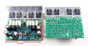
I have plans to build your kit LJM 7 with 4 Mosfets per channel to fix the problem with power dissipation at Hi power with 4 ohm loads.
I have plans to build your kit LJM 7 with 4 Mosfets per channel to fix the problem with power dissipation at Hi power with 4 ohm loads.
You can actually use L15. It is better than L7.Hi LJM,
I have plans to build your kit LJM 7 with 4 Mosfets per channel to fix the problem with power dissipation at Hi power with 4 ohm loads.
You mean you need high pitch adjustment. Bass adjustment function.I`m looking for a preamp with tone controls with NE5532 or OPA2134 can you suggest-me one?
I don't like amplifiers with high and low tone adjustment functions. So I can't recommend it.
If the high tone is necessary, the low tone is adjusted. I recommend using EQ software in the computer.
About LJM L20 SE, my new post:
https://www.audiosciencereview.com/...ation-for-2-0-speaker-amp.10522/#post-1286808
https://www.audiosciencereview.com/...ation-for-2-0-speaker-amp.10522/#post-1286808
It's a good idea but for me it's not practical because I Have analog audio sources like FM Tuner, Phono Turntable etc. For my digital sources I use a computer equalizer software.You can actually use L15. It is better than L7.
You mean you need high pitch adjustment. Bass adjustment function.
I don't like amplifiers with high and low tone adjustment functions. So I can't recommend it.
If the high tone is necessary, the low tone is adjusted. I recommend using EQ software in the computer.
I wouldn't want to have to divert the sound from my analog sources and pass them through my computer.
I found the L15 board that you are talking about on Aliexpress but it is only assembled, not in a kit to assemble. Could you send me the schematic of it?
The circuits of these amplifiers are not much different.I found the L15 board that you are talking about on Aliexpress but it is only assembled, not in a kit to assemble. Could you send me the schematic of it?
Only the number of transistors is different.
Hi LJM, I have an LJM USB to SPDIF board which uses a PCM2704 chip. According to the Texas data sheet the PCM2704 supports digital volume and mute control functions (the PCM2706/7 chips do not). However the remote control volume and mute functions are not working for me when the SPDIF board is used between my media PC and an outboard DAC. Am I missing something here?
Pcm2704 I often use it to test my DAC, cs4398 SPDIF interface.Hi LJM, I have an LJM USB to SPDIF board which uses a PCM2704 chip. According to the Texas data sheet the PCM2704 supports digital volume and mute control functions (the PCM2706/7 chips do not). However the remote control volume and mute functions are not working for me when the SPDIF board is used between my media PC and an outboard DAC. Am I missing something here?
It is convenient to control the volume. It can be directly controlled in Windows 7 or windows 10.
I have an extra 500VA toroid transformer with 30,000ufx2 capacitors. I have approximately +- 50VDC rails. I need to build a rock solid 2-4ohm capable subwoofer mono amplifier.
Which amp is the best solution. It is strictly subwoofer duty and needs to be very current capable.
Any suggestions which is the best board to use?
Which amp is the best solution. It is strictly subwoofer duty and needs to be very current capable.
Any suggestions which is the best board to use?
L20V10 , L20SE 。I have an extra 500VA toroid transformer with 30,000ufx2 capacitors. I have approximately +- 50VDC rails. I need to build a rock solid 2-4ohm capable subwoofer mono amplifier.
Which amp is the best solution. It is strictly subwoofer duty and needs to be very current capable.
Any suggestions which is the best board to use?
You should not use any class D amplifier.
Attachments
- Home
- Vendor's Bazaar
- LJM Audio