Regarding REW, I usually have the step by step instructions on a tablet, while running the program on a laptop.
Just take it slowly and one step at a time.
If you are using a USB mic, then the miniDSP has some good instruction regarding using REW with their UMIK-1 or 2.
Just take it slowly and one step at a time.
If you are using a USB mic, then the miniDSP has some good instruction regarding using REW with their UMIK-1 or 2.
Member
Joined 2003
No one has mentioned a turntable (yet), so let's try not to confuse the guy further.. Axis orientations as far as VituixCAD is concerned is detailed in the measurement guide.

I do not get what you are saying?I think you have to be careful with the phrasing used regarding the co-ordinates.
If you are taking horizontal measurements while rotating the speaker (say on a turntable), then you are rotating about the Y axis, but taking measurements on the X plane.
If you tilt the speaker forward and backward, you are rotating about the X axis, and taking measurements on the Y plane.
You're right.No one has mentioned a turntable (yet), so let's try not to confuse the guy further.. Axis orientations as far as VituixCAD is concerned is detailed in the measurement guide.
But I was only using "turntable" as a way of clarifying the rotational axis. i.e. the Y axis.
I just found the measurement guide a little confusing when describing rotational axes.
Measurement guides are not talking about rotations axles. Just cartesian coordinate system for driver location, on-axis (drivers's axis), off-axis (not driver's axis) and hor & ver planes.I just found the measurement guide a little confusing when describing rotational axes.
I'm quite ready to change license agreement so that Umik-1 users won't have permission to use VituixCAD. That mic and users are just pain in the a** 🙂
Name of the program is VituixCAD. No R.VIRTUIXCAD
I build a 2-channel measurement system for around 20 euro. This include mic (EM258 capsule) and phantom power. Im sure my measurement as accurate as Umik-1 etc...I'm quite ready to change license agreement so that Umik-1 users won't have permission to use VituixCAD. That mic and users are just pain in the a** 🙂
EM258 capsule is very linear and "new"version of the famous panasonic WM-61a.
I took a measurement for the tweeter. The peak was at eg 3.25ms for the mid driver it was at 3.35ms.Can you elaborate on this. Which setting you need to make in the different screens? I think mosyly in the measurement and preference/analysis window.
Follow the instructions in the measurement guide. Page 9 of the measurement guide for REW details windowing settings for export of data. Following this instruction you will achieve success. There are a few things to note, but will mostly be done automatically if you simply follow all the settings outlined in the document. The window reference time should be at or near the peak of the impulse, and must remain in the same location for all measurements, for all drivers.
"The window reference time should be at or near the peak of the impulse, andmust remain in the same location for all measurements, for all drivers"
Does this mean I need to move the windows reference time for the mid to be 0,1ms ahead of the peak? Or just leave them where they are?
I guess you mean DELAY on driver tab can remain empty.This ensures that all measurements have captured phase that includes any acoustic delays, so z axis offset can remain at 0 provided that mic distance is the same for all measurements, all drivers.
Is it possible to derive the distance from a first test measurement on the tweeter? In the test-result a distance is given.If you follow the instructions, you will enter a timing offset equal to the distance from mic to baffle so the reference start time of t=0 will already be at the impulse start.
You will see that the location of the impulse will move around a bit from measurement to measurement at various angles. The left window will ensure that even if the window start is in front of the impulse, the frequency response is still accurately captures, you will simply have some negative phase in the measurement.
This phrase seems to come back a few times in the manual.
"Remove all measurements from the list."
What does it mean? 🤔 It's not very clear.
I think we are talking about different things,though but still very helpful information.
I was interested in the settings for taking measurements and particular settings on measurement and pref/analysis window. More particular the settings in red window.
Going through the documentation once again I'm surprised how powerful this VITUIXCAD-tool is! Amazing really. 👍
Attachments

Last edited:
Made some measurements and using the manual and comments from @DcibeL to guide me.
Seem in the meanwhile some changes have been made to REW.
Now there is an option for IR windows to save and keep reference time.
In the manual export use custom resolution 48 PPO ; and 1/24 smoothing should be selected.
There is now an option for 96 PPO and select smoothing.
It took me a lot of time to make 3 driver measurements on 0-15-30-45 degree horizontal.
I should make a turning-table to make it a little easier.
I can understand why some people take a shortcut and try to measure all drivers on listening-axis.
How about phase and minimum phase? What should I do with that to make proper XO-design? 🤔
Attachments

Last edited:
Member
Joined 2003
Any 2-channel system is a far better solution than UMIK for this purpose. UMIK is created by a DSP company, for use with DSP systems. They technically don't need 2-channel as you can align drivers my taking live measurement and adjusting delay in the DSP, there's an instruction on miniDSP application section of the site, but if you intend to design with DSP and use of VituixCAD, stick with at least a semi-dual configuration. Just say no to USB mics!I build a 2-channel measurement system for around 20 euro. This include mic (EM258 capsule) and phantom power. Im sure my measurement as accurate as Umik-1 etc...
EM258 capsule is very linear and "new"version of the famous panasonic WM-61a.
Member
Joined 2003
DO NOT move the reference time. If you set it at 3.25ms for the tweeter, you will set it at 3.25ms for the woofer, and the 0.1ms of delay will be captured in the frequency response file. You can think of a movement in window reference time in the same way as physically moving the mic with regards to phase.I took a measurement for the tweeter. The peak was at eg 3.25ms for the mid driver it was at 3.35ms.
"The window reference time should be at or near the peak of the impulse, andmust remain in the same location for all measurements, for all drivers"
Does this mean I need to move the windows reference time for the mid to be 0,1ms ahead of the peak? Or just leave them where they are?
There are only a few simple rules to follow to ensure accurate phase/delay is captured in your measurements:
- mic distance to speaker baffle must stay the same for all measurements
- window reference time must be the same for all measurements
Delay in the driver tab, z axis offset in the crossover. There are only a few exceptions like the slanted baffle, or stepped baffle where you might enter z axis offset.I guess you mean DELAY on driver tab can remain empty.
I wouldn't, just measure physically and accurately as possible, and write down the distance when you save the file. We are talking distance of millimeters between tweeter and midrange so you want to minimize any error in this distance to get accurate phase interaction in the crossover design.Is it possible to derive the distance from a first test measurement on the tweeter? In the test-result a distance is given.
File menu -> Remove all measurements. It means to start fresh.This phrase seems to come back a few times in the manual.
"Remove all measurements from the list."
What does it mean? 🤔 It's not very clear.
Default settings there are fine, you can leave that as-is.I think we are talking about different things,though but still very helpful information.
I was interested in the settings for taking measurements and particular settings on measurement and pref/analysis window. More particular the settings in red window.
Going through the documentation once again I'm surprised how powerful this VITUIXCAD-tool is! Amazing really. 👍
Member
Joined 2003
Instructions will have you use the "apply windows to all" button. This is crucial to force all measurements to use the same reference time. Smoothing settings are mostly inconsequential, like I said you can smooth the measurements on the fly in the driver tab of VituixCAD. Feel free to export using different settings and compare the results.Made some measurements and using the manual and comments from @DcibeL to guide me.
Seem in the meanwhile some changes have been made to REW.
Now there is an option for IR windows to save and keep reference time.
In the manual export use custom resolution 48 PPO ; and 1/24 smoothing should be selected.
There is now an option for 96 PPO and select smoothing.
You can forget the term "minimum phase", you will use measured phase. Min phase is just band-aids for USB mic users or traced data.It took me a lot of time to make 3 driver measurements on 0-15-30-45 degree horizontal.
I should make a turning-table to make it a little easier.
I can understand why some people take a shortcut and try to measure all drivers on listening-axis.
How about phase and minimum phase? What should I do with that to make proper XO-design? 🤔
Remember that 0-180 degrees is needed for proper result of Power & DI chart. Yes, it's a tedious process, but an hour or two is worth the effort for a speaker that you will enjoy for years to come.
Ok understood. Just wanted to clarify that I didn't misinterpreted itDO NOT move the reference time. If you set it at 3.25ms for the tweeter, you will set it at 3.25ms for the woofer, and the 0.1ms of delay will be captured in the frequency response file. You can think of a movement in window reference time in the same way as physically moving the mic with regards to phase.
There are only a few simple rules to follow to ensure accurate phase/delay is captured in your measurements:
If you are following the instructions, you will set the timing offset equal to the physical mic distance when taking the measurements. "timing offset" mentioned on page 4. By doing so, the window reference time can simply remain at zero when you process the files (page 9).
- mic distance to speaker baffle must stay the same for all measurements
- window reference time must be the same for all measurements
What about R and T parameters? Is it included in some graph with the axis's ? I only seen graphs with X,Y,ZDelay in the driver tab, z axis offset in the crossover. There are only a few exceptions like the slanted baffle, or stepped baffle where you might enter z axis offset.
An hour or two...I only took the 0-15-30-45 degree measurements in that time frame. Turing the speaker and keeping the distance isn't easy and took a lot of rechecking.Instructions will have you use the "apply windows to all" button. This is crucial to force all measurements to use the same reference time. Smoothing settings are mostly inconsequential, like I said you can smooth the measurements on the fly in the driver tab of VituixCAD. Feel free to export using different settings and compare the results.
You can forget the term "minimum phase", you will use measured phase. Min phase is just band-aids for USB mic users or traced data.
Remember that 0-180 degrees is needed for proper result of Power & DI chart. Yes, it's a tedious process, but an hour or two is worth the effort for a speaker that you will enjoy for years to come.
I really need to make a turntable.....
Just to absolutely sure I'm doing the right thing.
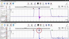
Below a picture of the impuls meting from my tweeter at 0 degrees (top) and 45 degrees (bottom).
As you notice the REF marker is at the peak of the impuls for both measurements.
After adjusting the IR window the REF marker is moved to position 0ms for the 45 degree measurement, same as it was originally for the 0 degrees measurement.
After this the files can be exported to VITUIXCad.
Attachments
Member
Joined 2003
I'm not sure I understand what you're asking. For a flat baffle, Z = 0, R=0, T=0. We talked above about how a slanted baffle would be tilted forward for ease of measurement, so it's treated as a flat baffle 90 degrees to the floor for the measurements. When designing the crossover for the slanted baffle, you would then enter the tilt value equal to the slope of the baffle, and Z axis would be the physical distance that results from the slope.What about R and T parameters? Is it included in some graph with the axis's ? I only seen graphs with X,Y,Z
For example, a 2-way speaker baffle with 5 degree slope, and drivers are separated by 200mm centre to centre. For this baffle arrangement you would enter a tilt of 5 degrees for both tweeter and woofer, and the woofer would have a Z offset of -17.4mm.
I don't have a fancy turntable setup, its tedious but the process should not take that long. I have a polar chart that I laminated and tape to the floor, to keep the angle and rotation centre and the front centre position of the baffle. The mic stays put, recheck of distance needed only when I change elevation for the next driver. Then its just measure, rotate, repeat.An hour or two...I only took the 0-15-30-45 degree measurements in that time frame. Turing the speaker and keeping the distance isn't easy and took a lot of rechecking.
I really need to make a turntable.....
Starting to feel like a broken record 😉. Follow what it says on page 9 of the guide. Your windowing looks fine, just open the IR windowing settings, hit "apply windows to all", then export.Just to absolutely sure I'm doing the right thing.
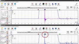
Below a picture of the impuls meting from my tweeter at 0 degrees (top) and 45 degrees (bottom).
As you notice the REF marker is at the peak of the impuls for both measurements.
After adjusting the IR window the REF marker is moved to position 0ms for the 45 degree measurement, same as it was originally for the 0 degrees measurement.
After this the files can be exported to VITUIXCad.
Last edited:
Member
Joined 2003
I'll link here to a post where someone built a very well functioning rotating setup. It's not motorized automation, but for manual worry free operation this is a rather good jig.
https://techtalk.parts-express.com/forum/tech-talk-forum/1475497-speaker-measurement-stand
https://techtalk.parts-express.com/forum/tech-talk-forum/1475497-speaker-measurement-stand
Member
Joined 2003
It looks like the impulse is occuring before T=0 position. If you are applying a timing offset to the measurement process, I would suggest the offset is a bit too long. It's not a big problem, but you may find the phase response to look a bit odd, since it will be showing a negative phase rotation.Just to absolutely sure I'm doing the right thing.
Below a picture of the impuls meting from my tweeter at 0 degrees (top) and 45 degrees (bottom).
As you notice the REF marker is at the peak of the impuls for both measurements.
After adjusting the IR window the REF marker is moved to position 0ms for the 45 degree measurement, same as it was originally for the 0 degrees measurement.
- Home
- Design & Build
- Software Tools
- VituixCAD