If you want to buy any product. If you want to know my answer.Well... the NE5532 is for pre amps and can not output any current worth mentioning, the MA5332 can churn out 2x100W.
Seems to me like you are (very) intentionally misunderstanding, probably very funny but the joke does not really translate.
Find it somewhat peculiar that you are fine with making obvious and perhaps boundless insinuations but do not wish to stand by any "conclusions" derived from what you say.
Again, if this is humour - does not translate.
You are entitled to have your opinion, and you can speak it freely (within the forum rules), but merely having an opinion does not mean people will automatically agree to it.
I would be interested in what you think are the important aspects/differences between what you differentiate as "toys" and "proper" amplifiers, but if it comes with a sales pitch (starting to seem like it...) I have no interest in that.
My answer is simple. TDA2030A。 It's very good. You can buy two ICs for $0.2
Then PCB is not required. Buy some resistors. Connect. It works better than any class D.
In fact, I don't pay much attention to what others want to buy. Because I can produce anything.
For example, ma12070. I am designing and producing it in a week.
Although I never recommend these things. I don't use these things either. But it doesn't prevent me from selling them.
Or other class D. I can produce it. Cheaper than any business in the world.
Can you understand. So don't misunderstand what I recommend to make money. Because what I recommend is basically.
Something you can get without spending money.
OK you don't use it, you don't recommend it, you can design and produce in 1 week. Nice. You could do us a great favor by designing THE MA12070 device with good output filtering, film input caps etc. in just 1 week so constructive stuff.
Now back to the subject for those that do like the chip.
Now back to the subject for those that do like the chip.
Last edited:
I don't think many people understand that class D thd is different from analog amplifier.OK you don't use it, you don't recommend it, you can design and produce in 1 week. Nice. You could do us a great favor by designing THE MA12070 device with good output filtering, film input caps etc. in just 1 week so constructive stuff.
Now back to the subject for those that do like the chip.
This requires understanding the cause of thd.
Any amplifier. We can reduce gain. That is, the number of negative feedback. To reduce thd For example, 2030a or lm4766t. It defaults to 22 times the magnification of thd Or 32 times. As long as we reduce the magnification, thd will become very small. But the output volume is very low. This makes no sense.
This is what class D actually does. It reduces the magnification. Lower thd.. This is just dataIt looks good. But the practical application is not good.You just turn up the volume a little bit. You will find that it is not as easy to use as TDA 2030a.
Man don't you think we have heard enough? Many topologies seem inferior on paper but work out relatively OK in practice. If we would dislike MA12070 or class D in general this thread would not exist. I think this chip is a very good performer and a threat for classic amplification so to speak. Now have you started THE MA12070 design already? There are 6 days left.
To be honest I am champion in being off topic but I think we have a new number 1.
To be honest I am champion in being off topic but I think we have a new number 1.

I think many people have strange ideas. They can reject any suggestion.Man don't you think we have heard enough? Many topologies seem inferior on paper but work out relatively OK in practice. If we would dislike MA12070 or class D in general this thread would not exist. I think this chip is a very good performer and a threat for classic amplification so to speak. Now have you started THE MA12070 design already? There are 6 days left.
To be honest I am champion in being off topic but I think we have a new number 1.
Even if it is to ask him not to spend money. He will also refuse.
It reminds me whether I am discussing with the salesperson of Infineon.
You can rest assured that I will design it and give the information on it.
In addition, I found that many Chinese chip manufacturers also have similar chips.
I will also design it for free. For example, Shanghai chipstar IC
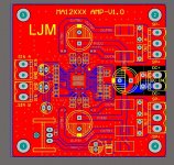
Attachments
Yes don't reject suggestions. Surprise us all with your skills, ljm_ljm. You may ironically be the best designer of a MA12070 PCB that get most out the chip. If you will do it: features like full output filtering, 5 mm pitch film input caps, MKDSN power supply connectors, ceramic caps preferably avoided so 5 mm film caps (but also SMD PCB pads just in case), pads for onboard linear regulator like LT/LD1084.
Enough similar stuff that exists but not many so well liked as the one in this thread.
Enough similar stuff that exists but not many so well liked as the one in this thread.
Last edited:
Received this yesterday and tried setting it up with piCorePlayer on a new 4B 8G. The board was recognized and squeezelite was successfully playing, but I couldn’t get sound out from the speaker terminals. When I get home after the weekend, I’ll dig into it more. I think some ALSA tweaking will be needed.Even less:
€ 23,23 34%OFF | 2X80W MA12070P + ESP32 Raspberry Pi Null 3 4B befestigen IIS I2S eingang hifi power verstärker bord
https://a.aliexpress.com/_mrSccU6
Did you get one of these, Radian?
I'm currently listening to one on my LMS 'network', but on a RPi Zero, with a PD power supply. Despite what it says on the board, do not supply 26v, I think the max is 20v. Assuming you have selected 'Merus Audio Amp' in Squeezelite, you should be good to go. You do, however, have to watch the limiter settings in Alsamixer, otherwise it will shutdown. Follow the instructions in Section 4.5.2 of the User Manual here: https://www.infineon.com/dgdl/Infin...N.pdf?fileId=5546d4626eab8fbf016eef8084096be6Received this yesterday and tried setting it up with piCorePlayer on a new 4B 8G. The board was recognized and squeezelite was successfully playing, but I couldn’t get sound out from the speaker terminals. When I get home after the weekend, I’ll dig into it more. I think some ALSA tweaking will be needed.
Did you get one of these, Radian?
I got 3 of those.
At the moment it's working fine with 2 12v Batteries in series. Fully charged that amounts to nearly 25v.
At the moment it's working fine with 2 12v Batteries in series. Fully charged that amounts to nearly 25v.
I got 3 of those.
At the moment it's working fine with 2 12v Batteries in series. Fully charged that amounts to nearly 25v.
According to this post by the board designer, you shouldn't be running over 22V:
https://www.diyaudio.com/community/threads/infineon-ma12070-class-d.347422/post-6814624
Yummy,Of course I already build the part with the Neutrik input transformers when I found these. Very heavy iron with 970 gram each. Flat from 20 to 20 kHz and 1:1, 2:1 and 1:2. LARGE.
I received 6 Haufe NF Übertrager that came on a board used in Studio Installations. I will give them a try.
I guess I will reduce the voltage then.According to this post by the board designer, you shouldn't be running over 22V:
https://www.diyaudio.com/community/threads/infineon-ma12070-class-d.347422/post-6814624
Bummer 2x12v was very convenient
Yes don't reject suggestions. Surprise us all with your skills, ljm_ljm. You may ironically be the best designer of a MA12070 PCB that get most out the chip. If you will do it: features like full output filtering, 5 mm pitch film input caps, MKDSN power supply connectors, ceramic caps preferably avoided so 5 mm film caps (but also SMD PCB pads just in case), pads for onboard linear regulator like LT/LD1084.
Enough similar stuff that exists but not many so well liked as the one in this thread.
Attachments
Nice start but no film input caps (4 pieces) and no balanced input/opamp circuit to make balanced balanced so the chip will definitely hiss. Output connectors could be the 2 pin version. Decoupling caps of the chip should be X7R as minimum standard so larger types. My personal question is if if makes sense to use TH film caps for decoupling despite their higher inductance. Why? In many cases where I replace the in that regard superior ceramic caps the device performs better instead of worse. For the input caps this is a 100% clear improvement too.
Input section can also exist of a unbalanced/bal transformer of Far East origin (so affordable) coupled with an onboard volume control like the standard Alps RK27. Resistors in 0805 for ease of soldering and caps at least 0805 to even 1210 for the 10 µF types (or 5 mm film if we are not afraid). With both 1210 and 5 mm TH pads things can be tested. In my experiments I found the chip performing nicer with regulated voltage and no SMPS so I would include pads for a 5A TO247 LDO reg with heatsink, 30 mm 10.000 µF 35V snap in filter cap and Schottky rectifier diodes.
Contrary to most devices we see on the market this PCB should be to aim for (subjectively) highest performance not lowest cost/highest margins. So against all normal (?!) design considerations aim for highest quality and high cost and then scale down if necessary. We see enough hampered designs without output filtering, gazillion opamps of unknown origin, armies of Class III caps and cheapness all around. Point being that these cheap devices already perform quite nice due to MA12070.
If the IC would be simple to solder I would already have made my own PCB. However I think it is slightly over the threshold of average level DIYing.
Last edited:
Input section can also exist of a unbalanced/bal transformer of Far East origin (so affordable)
These trafos will do the trick - with trafo coupling no caps are needed on the MA12070 side, the CT goes to the chip's own mid-rail reference (pin20) : https://www.aliexpress.com/item/325...f16580375932226072e566a!12000015960569527!sea
coupled with an onboard volume control like the standard Alps RK27.
4 channel RK27 doesn't come cheap : https://youdaelectronics.com/products/alps-rk27-4-channels-10k
With a middle point transformer and the middle point connected to GND there will be 2.5V from each winding to GND and both MA12070 and transformer are no fan of this. I already tested this and it required the standard 2 high quality caps per channel. Normally one connects the secondary middle point to the primary/RCA GND and then 2 caps are needed as these transformers don't like DC at all. From input to input the voltage is nearly 0V. You could look at the commercial products of a member here called abraxalito that sells a TDA8932 amplifier with transformer inputs. It seems he solves it with a large value cap from the transformer middle point and reference voltage pin to GND.
One does not need a 4 channel potentiometer when using unbalanced RCA inputs, RK27 and then an unbalanced/balanced transformer. In many cases a buffer opamp or DCB1 style buffer seems a necessity but then added complexity when wanting symmetric power supplies. Aargh....
One does not need a 4 channel potentiometer when using unbalanced RCA inputs, RK27 and then an unbalanced/balanced transformer. In many cases a buffer opamp or DCB1 style buffer seems a necessity but then added complexity when wanting symmetric power supplies. Aargh....
Last edited:
With a middle point transformer there will be 2.5V on each winding to GND. I already tested this and came up with just 2 high quality caps per channel. These transformers don't like DC at all.
I tested this too, works fine without caps. No DC on the trafo.
One does not need a 4 channel potentiometer when using unbalanced RCA inputs, RK27 and then an unbalanced/balanced transformer.
Indeedy but driving a trafo via a pot isn't ideal, trafos add distortion when their source impedance is high. Best drive them with as low impedance as possible.
Ljm _ljm The inputs of your board are not balanced ... it's not the best way to use this chip ...🤓
Oops...sorry...Already noticed by Jean-paul...
Go forward !!!
I put my irs2092 chips back in the attic...and kept my tpa 3255.
My favorite is all the same MA 12070 infineon.
ljm_ljm, you can take inspiration from the infineon evaluation board...
And sell them for less...
That would be a bonus for everyone!!!!!
Go forward !!!
I put my irs2092 chips back in the attic...and kept my tpa 3255.
My favorite is all the same MA 12070 infineon.
ljm_ljm, you can take inspiration from the infineon evaluation board...
And sell them for less...
That would be a bonus for everyone!!!!!
- Home
- Amplifiers
- Class D
- Infineon MA12070 Class D