Track back through the inputs and outputs and you will find the problem. Check that all chips are aligned correctly (I've made that mistake)There is a problem with shift registers. I already check them with points (DL, DR and ground) - signal is not coming from them. Maybe one on them is defective?
Has anyone compared an SD Card player to a USB-I2S feed?
Yes - the yellow SD card player I referred to earlier, with Mori clocks, feeding i2s to 1862 dac... vs amanero also with Mori clocks feeding the same DAC. SD card player is just a bit ahead of USB, a little bit more resolution and refinement. Same power supply for both (regular 317 supply feeding LT3042).
Ultimately though, it comes down to what you are going to use the most. If SD cards are just too messy for you to use, then it is of little use, but the same can be said of just every part of audio.
Just to throw in some more foolery, and not to derail the thread - SLC cards sound marginally better than MLC cards. Costly though.

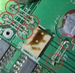
Its hard to see on your photo, but it looks like the two jumpers for DL and DR are open - but maybe its just that the photo isn't very clear. I think these were JP1 and JP2 on the older boards.There is a problem with shift registers. I already check them with points (DL, DR and ground) - signal is not coming from them. Maybe one on them is defective?
Fran
IRC the PCM170x +/5Vd,Va (Vcc, Vdd) supplies have to come up at more or less the same time, or the chips can get wonky. It looks like you used some pretty hefty caps on those rails, which may be creating time-constants that are throwing off the timing of the chip on startup.
It's a long shot, but if you've checked everything else...
It's a long shot, but if you've checked everything else...
In one of the old datasheets TI goes so far as to recommend there is no advantage to using different supplies for Vcc/Vdd, and if you guys are coming from 12V/5V AD1862 circuits you may be using different supplies on the PCM1702 as well
Thanks for that hint.Yes - the yellow SD card player I referred to earlier, with Mori clocks, feeding i2s to 1862 dac... vs amanero also with Mori clocks feeding the same DAC. SD card player is just a bit ahead of USB, a little bit more resolution and refinement. Same power supply for both (regular 317 supply feeding LT3042).
Ultimately though, it comes down to what you are going to use the most. If SD cards are just too messy for you to use, then it is of little use, but the same can be said of just every part of audio.
Just to throw in some more foolery, and not to derail the thread - SLC cards sound marginally better than MLC cards. Costly though.
Seems to me the difference you describe is subttle enough to comes from the difference of layout and passive parts and not necessarily from the sd card choice VS async or slaved USB.
I will not invest in a 400 euros Trans SD card reader then over a an USB Wave I/O for instance. Or even better I would go for a design where all is in the same pcb with a proven design : Aya5, Miro with embeded USB board ? Crystek oscillator on board with the acrylic decoupling cap for it and a good passive parts choice ?
If anyone interrested I would be happy to participate to offer a little project to the diya communauty... I am enjoying borring holidays at the countryside, lol. Miro, is there a way to work from your gerbers with Kicad for instance ?
A good angle.Its hard to see on your photo, but it looks like the two jumpers for DL and DR are open - but maybe its just that the photo isn't very clear. I think these were JP1 and JP2 on the older boards.
Fran
Attachments

same here, no sound come out, i checked all +/- voltage all correct, so i change the bit and sample rate to 16/44.1, but still no sound.
@chi0001 and @sworder84 Both of you have the same experience? No signal from shift registers? 🤔There is a problem with shift registers. I already check them with points (DL, DR and ground) - signal is not coming from them. Maybe one on them is defective?
Is it the same without DAC chips (when the PCM1702 is pulled out from PCB)?
Last edited:
... seems I had a bad idea... lol.🤣.
Okay time to hunt the butterflies, visit french South-West Dordogne castles and drink wines instead ! 😎
Okay time to hunt the butterflies, visit french South-West Dordogne castles and drink wines instead ! 😎
Yes, i also took out the chips and made the measurements without. The result is same - no signal from 74HCT164D.@chi0001 and @sworder84 Both of you have the same experience? No signal from shift registers? 🤔
Is it the same without DAC chips (when the PCM1702 is pulled out from PCB)?
Guys, what solder wire are you using? This doesn't look very good, it's probably not SnPb solder, if it's only Sn then you should go with a higher soldering iron temperature. Any solder joint like this could be a potential problem and could have easily destroyed both PCM1702s.A good angle.
It would be best if you first test the power supply, shift registers and op. amps and then insert the PCM1702.
And single +/-5V is enough for PCM1702, there is no need for double power supply because there is no improvement.
From PCM1702 ds;
POWER SUPPLIES
Refer to CONNECTION DIAGRAM for proper connection
of the PCM1702. The PCM1702 only requires a ±5V sup-
ply. Both positive supplies should be tied together at a single
point. Similarly, both negative supplies should be connected
together. No real advantage is gained by using separate
analog and digital supplies. It is more important that both
these supplies be as “clean” as possible to reduce coupling
of supply noise to the output. Power supply decoupling
capacitors should be used at each supply pin to maximize
power supply rejection, as shown in CONNECTION DIA-
GRAM regardless of how good the supplies are. Both
commons should be connected to an analog ground plane as
close to the PCM1702 as possible.
Attachments
I just now ordered the last of my components and started making a 1862 DAC. I noticed Digikey is listing components for Rochester as a marketplace product. Digikey lists the AD1862 for sale and says it will ship in approximately 10 days from Rochester. Of course, it still has the same minimum sales amount, which is for this product, qty 14 at $22.93/ea, for a total of $321.02. Has anyone tried this? I guess I am speaking to Paddy first.
BTW, thank you Paddy for all your hard work getting the chips in the past. Maybe it can continue?
BTW, thank you Paddy for all your hard work getting the chips in the past. Maybe it can continue?
No, I don't have an osilloscope, only measure voltage on 14 pin and ground of each Nexperia and also DL DR and ground.Did you track back through the inputs and outputs of each shift register?
@ Grunf,
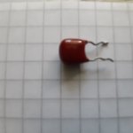
Any idea of what dielectric it is please ? Took from an old Philips.
Seems to me mylar but maybe ceramic class 2 ? But not the same than military radial ceramic class 2 in squared plastic case for instance...
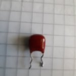
Any idea of what dielectric it is please ? Took from an old Philips.
Seems to me mylar but maybe ceramic class 2 ? But not the same than military radial ceramic class 2 in squared plastic case for instance...
Attachments
You don't need a scope - just set your multimeter to DC and measure. The high frequency of the signal fools the meter into thinking that its DC. Expect somewhere between 0.7 and 1.6V or so - but you will only have data when something is playing.No, I don't have an osilloscope, only measure voltage on 14 pin and ground of each Nexperia and also DL DR and ground.
Look, I gotta say - your soldering on all of those ICs doesn't look great, IC4 in particular. If this was in front of me, I would be using a magnifying loupe, I would flood the area with flux, and then with a clean tip I'd touch each pin with the iron. Then, I would use a meter on continuity mode and sharp point tips and check for continuity between each track and each leg of each chip just where it enters the body of the chip. I'd also check you don't have shorts between pins too.
Something else you could do - check for Data at the input, and see where the signal stops as it passes through the shift registers.
Lose that silver solder and use some regular flux cored solder. Having a good connection that lasts really well beats the hell out of the difficulty of running silver bearing solder.@grunf now I have a Tchernov audio solder with silver (SFS/AG). This is a good solder. Unfortunately I was soldering with old iron tip and that's why the result a little poor quality)
@sworder84, I know how you feel using an old iron tip. It is tough. But I tell you, once I used a temperature controlled Hakko soldering station at work, I realized I could never go back. I bought a Hakko 951 station for myself. Those rough solder joints on your smd chips are likely hiding some problems. The good news is that you can easily and quickly redo all those smd solder joints. Like several Youtube videos on soldering smd parts show, apply flux from a tube onto one row and drag a small tip across that row. I think you will make beautiful looking solder joints, and I think your shift register problem goes away.
- Home
- Source & Line
- Digital Line Level
- DAC AD1862: Almost THT, I2S input, NOS, R-2R