Also that screw terminal on the ground point for the output looks a bit funny, you have checked for good connection there to the board and the jack I hope?where is the critical points
I found the culprit!!! The left RCA ground tab was directly touching the chassis with the plastic separator on the other side. What a bonehead mistake! I have music that sounds like music. Let the critical listening and fine tuning begin! Thanks, all.
Attachments
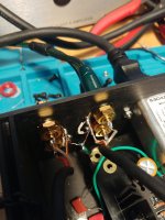

See, I had a feeling it was GND-related... 😉I found the culprit!!! The left RCA ground tab was directly touching the chassis with the plastic separator on the other side. What a bonehead mistake! I have music that sounds like music. Let the critical listening and fine tuning begin! Thanks, all.
It's an awesome headamp. Interested in hearing your impressions
Hello berkbear,
this is the reason why I mount the groundtab between the two nuts - If I use these Neutrik/Rean-RCAs.
Greets
Dirk
this is the reason why I mount the groundtab between the two nuts - If I use these Neutrik/Rean-RCAs.
Greets
Dirk
@sp33ls You were right! By focusing on the GND area, it led me to the problem. thanks for your guidance.
@A Jedi you were also right. By focusing on signal path, that led me to the RCA, which led me to the grounding post. Thanks for your help, as well.
Lesson learned: Follow the signal to all its various points, most importantly to GND if it sounds off.
Much appreciation!!!
@A Jedi you were also right. By focusing on signal path, that led me to the RCA, which led me to the grounding post. Thanks for your help, as well.
Lesson learned: Follow the signal to all its various points, most importantly to GND if it sounds off.
Much appreciation!!!
Great advice, as well!!!Hello berkbear,
this is the reason why I mount the groundtab between the two nuts - If I use these Neutrik/Rean-RCAs.
Greets
Dirk
Hello all,
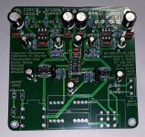
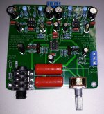
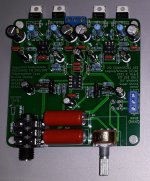
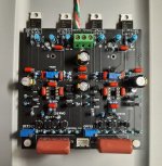
I recently finished my first Whammy build and had a ton of fun with it. I designed my own custom steel chassis, and then I water jetted and welded it together myself.


I previously had no experience with HiFi audio, so I didn't really know what to expect when it was finished. But I have a couple of questions for you all, who are far more experienced that I.
1. Is it normal to experience ear fatigue when listening at even normal to low volume? The amp has run for a collective 48 hours probably at this point, and I read online somewhere that the capacitors should be burned in by now. The best word I can use to describe the feeling is "harsh," and the only other time I've felt that is in my university electronics lab when somebody played out a high-frequency tone on loudspeakers. That situation was obviously much more pronounced, and I had a headache for hours afterwards. With the Whammy, the sound itself is excellent and there are no other noticeable issues. A few possible culprits: I am using a 100k pot instead of a 50k or 10k; my headphones are 250 ohm Beyerdynamic DT990's ; I am using 2 ohm resistors in place of the recommended 5.1 ohm at R38, R21, R37 and R20.
2. In 6L6's original post for the build guide, there is a clean looking square wave toward the bottom. I sent a square wave into my amp and noticed an extremely pronounced shoulder at the output. Is that normal, or could this be part of the harshness problem? Thanks in advance!

I recently finished my first Whammy build and had a ton of fun with it. I designed my own custom steel chassis, and then I water jetted and welded it together myself.
I previously had no experience with HiFi audio, so I didn't really know what to expect when it was finished. But I have a couple of questions for you all, who are far more experienced that I.
1. Is it normal to experience ear fatigue when listening at even normal to low volume? The amp has run for a collective 48 hours probably at this point, and I read online somewhere that the capacitors should be burned in by now. The best word I can use to describe the feeling is "harsh," and the only other time I've felt that is in my university electronics lab when somebody played out a high-frequency tone on loudspeakers. That situation was obviously much more pronounced, and I had a headache for hours afterwards. With the Whammy, the sound itself is excellent and there are no other noticeable issues. A few possible culprits: I am using a 100k pot instead of a 50k or 10k; my headphones are 250 ohm Beyerdynamic DT990's ; I am using 2 ohm resistors in place of the recommended 5.1 ohm at R38, R21, R37 and R20.
2. In 6L6's original post for the build guide, there is a clean looking square wave toward the bottom. I sent a square wave into my amp and noticed an extremely pronounced shoulder at the output. Is that normal, or could this be part of the harshness problem? Thanks in advance!
The DT990 has massive peaks in FR in the upper mid and lower highs. Precisely areas that cause fatigue. It's been measured many times - just google it. Perhaps whatever you were using to power it until now was rolling off the high end?
Last edited:

Yes, it is the one I posted here: https://www.diyaudio.com/community/threads/whammy-pass-diy-headphone-amp-guide.317803/post-6855694
DIY Disaster Averted.
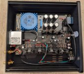
My Whammy is stuffed, assembled, and working as expected but I nearly blew it along the way.
First problem was the 7815 which had 30vdc input, gnd=gnd, and 9vdc output with 1k load. I was surprised because these regulators are rugged. The PSU worked with a new 7815.
After doing some testing, I decided to make some fixes for the heat caused by the large voltage drop in the regulators. I cut one of the AC jumper wires so that only one primary coil was active. This reduced the rectified voltage from 30vdc to 25vdc. Now the new voltage drop is 25-17 which seems better than the old 30-15. BTW I used green LEDs in the reference circuit.
But when I removed the PCB from the case for this mod, I was shocked to see that Q4 was not soldered. I suppose the pins were touching the pcb pads such that the circuit happened to work. But it could have been a disaster such as cooking my Oppo planar cans.
... Whew!
Another mod: I did not use a capacitor between the input jacks and AC ground .. there is a direct connection which could be easily changed. The Schuter power input is the starting point of all grounds. The case and the board standoffs are not grounded because of the black paint.
I drive the Whammy with a Schiit Modi 3 which is a USB DAC. It should be better than the computer's Realtec ALC1220 codec which is a complex multi-channel chip in the corner of a mini-itx board. I don't know how well it is supported by Linux.
I did some testing with "Area 31" (wav files) from David Chesky. It's a clean, total analog recording of a chamber music ensemble. Not my thing but it might be good for testing dynamics.
Attachments
Last edited:
Be aware: By using only 1 primary, you have reduced the power of the transformer to 6,5VA. The reason that the voltage have dropped to 25VDC is that the transformer is being pushed extremely hard. the transformer can only deliver 0.13A and maximum half that continiusly if you want it to live.
On my first build when I plugged it in, my home circuit breaker actually tripped. Didn't take long to look at the board to realise I did not cut the C13 and C23 legs. They were probably touching the case and tripped the breaker.
Or maybe they could've been 2 totally unrelated things, but I'm glad it happened.
Or maybe they could've been 2 totally unrelated things, but I'm glad it happened.
Sorry. That should be 12,5VA. So 0.25A maximum. and half that continuously.Be aware: By using only 1 primary, you have reduced the power of the transformer to 6,5VA. The reason that the voltage have dropped to 25VDC is that the transformer is being pushed extremely hard. the transformer can only deliver 0.13A and maximum half that continiusly if you want it to live.
- Home
- Amplifiers
- Pass Labs
- "WHAMMY" Pass DIY headphone amp guide