This is understood by most experienced engineers, and our lazy way of doing this is using a fader controller device that has a mute and solo button. We set it up so mute one of the tracks, then push the mute and solo at the same time on that same track, and it switches between the two. We close our eyes, hit both buttons a bunch of times so we dont know which is currently playing, then see if we can tell the difference between the two.Even more important, you need to start testing using a double-blind methodology or your results will definitely be skewed. That form of testing eliminates many uncontrolled biases, which unfortunately will strongly affect your results.
The concept is to present choice A, and compare to choice B without knowing which choice has the transformers. Then, compare each to choice C, which will be either A or B, and see if you can determine if it matches A or B. Choice C should be randomly assigned to A or B. It's not easy, and the simpler switching methods require the help of an assistant to remain fully blind, but just comparing the known transformer path to non-transformer path is loaded with expectation bias. Once you really clobber the 111C with hot levels, you'll no doubt pick it out correctly. But at normal, reasonable levels, the differences are very small and influenced by biases.
This is one rason the whole transformer color thing is a mess. Nobody tests it right.
I know, hardly scientific, but it's better than seeing which one we are listening to. I was able to pick out the 111C track about 75% of the time. Granted that's not scientific enough to put this matter to rest, but I am confident with my opinion on the matter. I feel I am more objective than most audio engineers when doing this stuff.
Regardless, I will say that I am not doing this because I think being able to hit the transformers harder will increase the quality of my work. I am doing this because I enjoy the challenge. I appreciate your input as well.
This circuit, similar to one used in the MCI JH-500C and 500D consoles, can produce +27 dBu. It's virtually identical to the MCI "Swinging Op Amp" except for being current-boosted by Q2/Q4.
If two were used in a fully-balanced driver you could reach +33 dBu. https://proaudiodesignforum.com/forum/php/viewtopic.php?f=6&t=927&p=10906
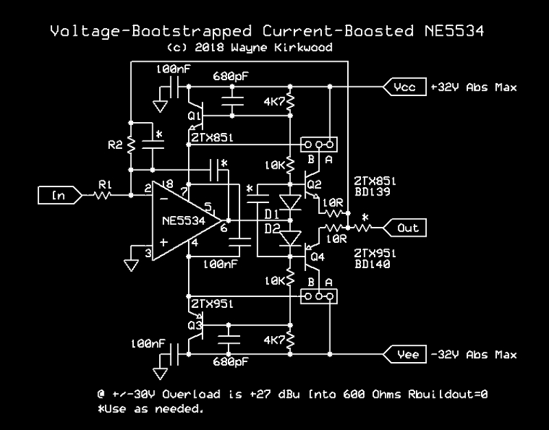
Several "*" compensation caps are shown, the one you want use is the Cfb directly around the op amp.
At the kind of peak currents seen in a fully-balanced BTL output the transistors should be larger and heatsinked such as the BD139/140.
Several of my Mastering Engineer clients use these in push-pull but they'll only do +27 dBu: https://ka-electronics.com/shop/index.php?route=product/product&product_id=67
Related reading "Bootstrapped Op Amp Articles": https://www.proaudiodesignforum.com/forum/php/viewtopic.php?f=12&t=699
Or you could use a power amp...
If two were used in a fully-balanced driver you could reach +33 dBu. https://proaudiodesignforum.com/forum/php/viewtopic.php?f=6&t=927&p=10906
Several "*" compensation caps are shown, the one you want use is the Cfb directly around the op amp.
At the kind of peak currents seen in a fully-balanced BTL output the transistors should be larger and heatsinked such as the BD139/140.
Several of my Mastering Engineer clients use these in push-pull but they'll only do +27 dBu: https://ka-electronics.com/shop/index.php?route=product/product&product_id=67
Related reading "Bootstrapped Op Amp Articles": https://www.proaudiodesignforum.com/forum/php/viewtopic.php?f=12&t=699
Or you could use a power amp...
Last edited:
The transformer data sheet lists +30 dBm at the low frequency design frequency of 30 Hz. This would be 1 watt but the data sheet lists this as 1.1 watt which would round off as +30 dBm.
The voltage required be 1.1 = Voltage squared divided by 600 ohms. Which is a bit under 26 volts RMS or a bit more than 36 volts peak. An amplifier designed for more than 85 watts at eight ohms could deliver this voltage. However as the RMS current requirement would be a bit less than 45 mA the delivered power would really be the one-ish watt required.
However using it as a 150 ohm to 600 ohm transformer would lower the voltage limit to under 13 volts RMS or a peak voltage of just above 18 volts. However the current required would go up to 90 mA RMS.
So his current gizmo can probably produce enough voltage from the differential outputs but will need current gain. Thus a pair of emitter followers should be adequate.
Of course if the transformer is not loaded by an actual 600 ohm load but rather the more typical 10,000 ohm load, then no buffer would be required.
I wish I understood the implications of this reply lol. Man I really need to learn more about this.The transformer data sheet lists +30 dBm at the low frequency design frequency of 30 Hz. This would be 1 watt but the data sheet lists this as 1.1 watt which would round off as +30 dBm.
The voltage required be 1.1 = Voltage squared divided by 600 ohms. Which is a bit under 26 volts RMS or a bit more than 36 volts peak. An amplifier designed for more than 85 watts at eight ohms could deliver this voltage. However as the RMS current requirement would be a bit less than 45 mA the delivered power would really be the one-ish watt required.
However using it as a 150 ohm to 600 ohm transformer would lower the voltage limit to under 13 volts RMS or a peak voltage of just above 18 volts. However the current required would go up to 90 mA RMS.
So his current gizmo can probably produce enough voltage from the differential outputs but will need current gain. Thus a pair of emitter followers should be adequate.
Of course if the transformer is not loaded by an actual 600 ohm load but rather the more typical 10,000 ohm load, then no buffer would be required.
In t
Is there a power amp you know of that is already set up with balanced outs at 600ohm?This circuit, similar to one used in the MCI JH-500C and 500D consoles, can produce +27 dBu. It's virtually identical to the MCI "Swinging Op Amp" except for being current-boosted by Q2/Q4.
If two were used in a fully-balanced driver you could reach +33 dBu. https://proaudiodesignforum.com/forum/php/viewtopic.php?f=6&t=927&p=10906
Several "*" compensation caps are shown, the one you want use is the Cfb directly around the op amp.
At the kind of peak currents seen in a fully-balanced BTL output the transistors should be larger and heatsinked such as the BD139/140.
Several of my Mastering Engineer clients use these in push-pull but they'll only do +27 dBu: https://ka-electronics.com/shop/index.php?route=product/product&product_id=67
Related reading "Bootstrapped Op Amp Articles": https://www.proaudiodesignforum.com/forum/php/viewtopic.php?f=12&t=699
Or you could use a power amp...
Never said "immeasurable". It's certainly measurable.I agree that we are getting into territory of whether the difference would be significant to the average listener, and my opinion would be no, that at these levels it does not. However I would disagree with your original notion that the difference is immeasurable.
But that has not been proven. You're doing biased sighted testing.While the difference in signal was low, it was clearly there, and to a trained engineer ear it is audible.
Yes, it is possible to perceive tonal differences, but its also a question of degree, and control of expectation bias. You can also train to perceive very low thresholds, but if you don't control bias you have mostly bias at those levels.And although it is music, the information in both files was the same, I believe the general perception of tone difference is something that can be reliably perceived, albeit maybe not by the average listener.
I agree that more level would produce more distortion, but these are literally some of the best transformers in the world. If you want distortion from them you've got a significant task. Again, use a power amp. If you want transformer distrotion at some more reasonable level, pick different transformers.I do believe that sending more level to these units would increase the affect, as we both understand that distortion increases as level is increased. It is that distortion change I am interested in hearing.
"Is there a power amp you know of that is already set up with balanced outs at 600ohm?"
Almost any power amp offering a "bridged" output could be used. You would add external resistors to increase the output impedance.
Almost any power amp offering a "bridged" output could be used. You would add external resistors to increase the output impedance.
I had to dig around to get the data sheet for the 123-BLCF, but found it. I'm not sure what you're thinking the design frequency is, but I don't see 30Hz listed. I do see these graphs, which are much more telling:The transformer data sheet lists +30 dBm at the low frequency design frequency of 30 Hz. This would be 1 watt but the data sheet lists this as 1.1 watt which would round off as +30 dBm.
...and you'd get a differet distortion characteristic.Of course if the transformer is not loaded by an actual 600 ohm load but rather the more typical 10,000 ohm load, then no buffer would be required.
Just look at the graphs, see if that helps.I wish I understood the implications of this reply lol. Man I really need to learn more about this.
You don't need a balanced output, just the 600 ohms. Power amps have nearly zero source Z, so a single 600 ohm resistor would do it, or if you like, a pair of 300 ohm resistors. Same for a bridged output, one or two resistors, doesn't matter.Is there a power amp you know of that is already set up with balanced outs at 600ohm?
When I hear "power amp" I think of an amp with only speaker terminal outputs. Are you all implying I convert those terminals to XLR (pin 2 being the + and pin 3 being the -, leaving pin 1 not connected)? Or am I misunderstanding what you all mean by power amp?Just look at the graphs, see if that helps.
You don't need a balanced output, just the 600 ohms. Power amps have nearly zero source Z, so a single 600 ohm resistor would do it, or if you like, a pair of 300 ohm resistors. Same for a bridged output, one or two resistors, doesn't matter.
You've got it. Just add the resistors before connecting to Pin 2 and 3.When I hear "power amp" I think of an amp with only speaker terminal outputs. Are you all implying I convert those terminals to XLR (pin 2 being the + and pin 3 being the -, leaving pin 1 not connected)? Or am I misunderstanding what you all mean by power amp?
The use of a power amp is quick and easy, you don't need to build much. Any amp in the 60 watt range will produce enough voltage into your transformers to get into saturation. The resistors are needed to allow more nonlinearity in the transformer, which is what you're after.
Well damn thats not a bad solution at all. Power amps can be had for quite low. And I believe I saw that the wattage needed was under 50watts, so that's even better. Actually I feel like I'd run into the problem of the amp being too powerful and barely being able to turn the gain knob up.You've got it. Just add the resistors before connecting to Pin 2 and 3.
Let me look at some options and I'll post them and hopefully you all can tell me what you think.
The rest of it is, if you drive the transformer, say 10dB higher than your normal studio levels, then you also need a 10dB pad at the output so it doesn't smash the input of whatever you connect it to. The pad can also provide a 600 ohm termination.Well damn thats not a bad solution at all. Power amps can be had for quite low. And I believe I saw that the wattage needed was under 50watts, so that's even better. Actually I feel like I'd run into the problem of the amp being too powerful and barely being able to turn the gain knob up.
Let me look at some options and I'll post them and hopefully you all can tell me what you think.
I mean this is the smallest power amp on sweetwaterYou've got it. Just add the resistors before connecting to Pin 2 and 3.
The use of a power amp is quick and easy, you don't need to build much. Any amp in the 60 watt range will produce enough voltage into your transformers to get into saturation. The resistors are needed to allow more nonlinearity in the transformer, which is what you're after.
https://www.sweetwater.com/store/detail/Servo120a--samson-servo-120a-power-amplifier
Does 60w per channel, 2 channel. I could definitely handle adding resistors and changing the output jack.. or even make a little converter cable. And you said I just need a 600ohm resistor per channel before it hits the 111C?? Is there a specific resistor brand/type that you recommend? Or any 600ohm resistor will do?
Currently I have a pair of -30db pads on the XLR jacks going into the interface so it doesn't clip the +20dbu max converters. Then I just bring the level back up once inside the DAW to get it back to what I want. Ideally I'd set up a potentiometer on the input but I'm fine with doing it in the DAW post conversion.The rest of it is, if you drive the transformer, say 10dB higher than your normal studio levels, then you also need a 10dB pad at the output so it doesn't smash the input of whatever you connect it to. The pad can also provide a 600 ohm termination.
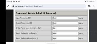
Although I just remembered that those -30db pads bring the ohms down to 150.. if Im going to go the power amp route I'll just do the pads correctly and build a T pad. But since you said the output will be unbalanced then I have to use the unbalanced calcs. I attached a screenshot of what the T pad calculator said the r values should be for -30db pad
Attachments
Last edited:
You'd want something like a 1 watt, 10%, 560 ohm. Close enough to 600, and you can't easily get 600 ohm resistors in a 1 watt.I mean this is the smallest power amp on sweetwater
https://www.sweetwater.com/store/detail/Servo120a--samson-servo-120a-power-amplifier
Does 60w per channel, 2 channel. I could definitely handle adding resistors and changing the output jack.. or even make a little converter cable. And you said I just need a 600ohm resistor per channel before it hits the 111C?? Is there a specific resistor brand/type that you recommend? Or any 600ohm resistor will do?
Your pads will be fine.Currently I have a pair of -30db pads on the XLR jacks going into the interface so it doesn't clip the +20dbu max converters. Then I just bring the level back up once inside the DAW to get it back to what I want. Ideally I'd set up a potentiometer on the input but I'm fine with doing it in the DAW post conversion.
Although I just remembered that those -30db pads bring the ohms down to 150.. if Im going to go the power amp route I'll just do the pads correctly and build a T pad. But since you said the output will be unbalanced then I have to use the unbalanced calcs. I attached a screenshot of what the T pad calculator said the r values should be..
Thanks a lot!For resistors, mouser.com or digikey.com.
Search for this part number on mouser.com:
PCF2C561K
Power amp and resistors ordered. Now we wait.For resistors, mouser.com or digikey.com.
Search for this part number on mouser.com:
PCF2C561K
- Home
- Source & Line
- Analog Line Level
- Line Amp Capable of +35dbu