This seems in line with my own experiments a while back with my custom USB Isolator: The Isolator was built for my DAC, an iFi iDSD Nano. I tried it with my DIY Low-noise Linear Regulated PSU with the Behringer as a DAC only and just by ear, I couldn't tell any difference. It did have a big audible difference with the iFi though, so my conclusion was the Behringer was sufficiently isolated so that it doesn't make any audible difference.dosen't make any change (with & without isolator)
However, note here that I didn't investigate further with the oscilloscope, nor have I tested with measurements the effects on the ADC side.
What a journey 🙂
Finally i did test all of them options.
I tried both plain usb cable directly from PC to Behringer, with the splitterbox and an good 5v switcher and finally with a highquality linear supply (dual lt3042)
I tried both with and without the USB isolator.
First off, the USB isolator don't do any difference in my setup, but again could be handy if i ever need to power a unit (DUT) with the PC usb supply? (Groundloop?!)
As Jan told some weeks ago, he did raise the voltage for the codec inside the Behringer with better thd figures.
I also tried this now, and verified with Behringer running some loopback at full scale, that the voltage was stable, which it was.
I did set the voltage to 4.89vdc (originally at 4.5vdc), but stranger things is that the thd figures raises when i do this, nomatter what i do it is worse than the stock setting at 4.5vdc. I'am sure i did it right.
For me, i think i reached the limit of my Behringer-mod, i tried a lot now so i can sleep better, knowing that i tried 😉
Anyway i end up with, just using a plain USB cable is very close to best option.
One thing i did was when i had the Behringer opened up several times is discovering that when touching the input level controller, the Behringer responded with noise and spikes and stuff, not much but i found a solution. I cured this by connecting the pot directly to GND, like when making preamp's and stuff.
Jesper.
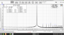
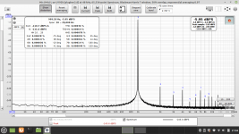
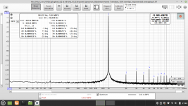
Attached loopbacks with different supply's, stock codec voltage at 4.5vdc on all. - Source Victor's 1KHZ osc.


Finally i did test all of them options.
I tried both plain usb cable directly from PC to Behringer, with the splitterbox and an good 5v switcher and finally with a highquality linear supply (dual lt3042)
I tried both with and without the USB isolator.
First off, the USB isolator don't do any difference in my setup, but again could be handy if i ever need to power a unit (DUT) with the PC usb supply? (Groundloop?!)
As Jan told some weeks ago, he did raise the voltage for the codec inside the Behringer with better thd figures.
I also tried this now, and verified with Behringer running some loopback at full scale, that the voltage was stable, which it was.
I did set the voltage to 4.89vdc (originally at 4.5vdc), but stranger things is that the thd figures raises when i do this, nomatter what i do it is worse than the stock setting at 4.5vdc. I'am sure i did it right.
For me, i think i reached the limit of my Behringer-mod, i tried a lot now so i can sleep better, knowing that i tried 😉
Anyway i end up with, just using a plain USB cable is very close to best option.
One thing i did was when i had the Behringer opened up several times is discovering that when touching the input level controller, the Behringer responded with noise and spikes and stuff, not much but i found a solution. I cured this by connecting the pot directly to GND, like when making preamp's and stuff.
Jesper.
Attached loopbacks with different supply's, stock codec voltage at 4.5vdc on all. - Source Victor's 1KHZ osc.
Attachments

Well done, quite thorough.
Is there a Battery test somewhere? You could even try various types of batteries.
Now you can do the same tests but with your amp within the chain. Results can be quite surprising here too.
Not sure about the actual cause of the even order harmonics but rectifying diodes would contribute harmonics for sure. Here, for powering musical gear, I'd prefer having even order over odd order.
For measurements, of course, we strive to minimise everything as much as possible.
By the way, in one of my posts quite a bit back now I believe in this thread, I showed how the interface, when situated on top of one of my Linear Reg PSUs, actually acts as an interference meter when connected to R.E.W.
The effect is more pronounced when I orient the interface's inputs near the top of the Linear Reg PSU: it's most probably picking up interference from the PSU's transformer.
This is especially important to take into account when using the Single-Ended modification. So generally, don't set it up atop another powered piece of gear.
Hi fellow diyers 🙂
I also wonder why even harmonics are higher, using a linear reg. - But i do belive it's the toroid transformer i use.
Well... I also tried my USB batterypack, with and without the USB-isolator, no change.
I think now, that the Behringer is to prone (thanks to the balanced board and some of the GND-fix i did) to have any use of the isolator.
Well well... I just coulden't resist, making my rig complete, so i build the loadresistor's (8ohm, 10K and 910ohm) into a shielded box.
I also created a bunch of different cables with plug's for different setup's. -It's nice to have for sure.
The loadresistor box actually do some good things to my setup. The noisefloor is going lower when using it, instead of having the resistors "open", it's also make things easier to use like this.
Will do some more DUT test... and also be testing @YashN mod to have a really comparing.
Today i tested some cheap Chinese ClassD amp. Noisefloot is higher than on my other amp's, but no 50, 100 etc... HZ spikes at all (I do realise that switchmode supply's are good these day's).
Btw. : I'am building this notchfilter, but i need to adjust it a bit for having exsact fundamental - Just not there yet to fully understand howto use it...
Jesper.
Ready to go! 👍 The notch filter generally goes like this: Gen>DUT>Notch Filter> Soundcard. The DUT will take the fundamental -1kHz- and give it at the output together with harmonic distortion. The notch filter will null the fundamental so the soundcard will see only the harmonics. Since these come at very low level, you can turn up the soundcard input without overloading it with the fundamental. This helps to keep low the residual distortion of the soundcard and have a better view at the DUT. To express this in numbers it will take calculations or some kind of calibration of the distortion analyzer that I'm not aware of.
This is perfect!
This was the explanation i needed to understand the basic's.
* I never understood that i needed to place the notch after the DUT, thank's @MagicBus
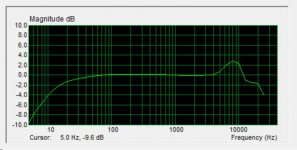
If i look at a loopback with notch like this [1KHZ osc] ---> [1KHZ Notchfilter] ---> [Behringer] (See picture)
I'am sure, i then need to offset this transfercurve to 0dB and export this as mic. calibration file?!
OR do trace arithmetic (notch/nonotch) and use this as the offset mic. calibration file?!
When mic. calibration file is loaded i need to enter the fundamental manuel (E.g Victor's osc. at 1V i set this fundamental at 1.000Vrms)
Then i think REW wil calculate the correct THD number's.
I just need to test for real and have this verified by someone expert.
I'am getting there 🙂
Could be very usefull.


Jesper.
This was the explanation i needed to understand the basic's.
* I never understood that i needed to place the notch after the DUT, thank's @MagicBus
If i look at a loopback with notch like this [1KHZ osc] ---> [1KHZ Notchfilter] ---> [Behringer] (See picture)
I'am sure, i then need to offset this transfercurve to 0dB and export this as mic. calibration file?!
OR do trace arithmetic (notch/nonotch) and use this as the offset mic. calibration file?!
When mic. calibration file is loaded i need to enter the fundamental manuel (E.g Victor's osc. at 1V i set this fundamental at 1.000Vrms)
Then i think REW wil calculate the correct THD number's.
I just need to test for real and have this verified by someone expert.
I'am getting there 🙂
Could be very usefull.
Jesper.
It would be nice if more knowledgeable people could chime in. FWIW, here is what I use to calibrate a diy mic for speakers measurements with ARTA. It's based on a commercial product but I modified the text file to adjust the frequency response to my mic. Not text book approach but it might be a starting point...
Attachments
Agree 🙂It would be nice if more knowledgeable people could chime in
Okay... i will try to explain how i think it should be done.
STEP 1.
EDIT :: This is with full input on the balanced board.
* Calibrate RMS level - internal generator giving 703mV.
* Measure the soundcard, using the internal generator, with and without notch. Do trace arithmetic (notch / nonotch). This gives the blue trace, near 0dB.
This trace is exported as .txt, to be loaded as mic. calibration file.
* Now load the calibration file.
I think so far it's correct?
Jesper.
Last edited:
STEP 2.
EDIT :: This is with full input on the balanced board.
With mic. calibrationfile loaded.
I send 0.7V from Victors into the notch and then into the Behringer.
I think it's the correct way ??? - Yes/No 🙂

Compared to Victors sending 700mV directly to Behringer, without notch and without calibration file

Jesper.
EDIT :: This is with full input on the balanced board.
With mic. calibrationfile loaded.
I send 0.7V from Victors into the notch and then into the Behringer.
I think it's the correct way ??? - Yes/No 🙂
Compared to Victors sending 700mV directly to Behringer, without notch and without calibration file
Jesper.
STEP 3.
This is with full input on the balanced board.
Confirm voltage calibration (Thanks for learning me this some time ago Salas)
With notch and calibration file ::

With no notch and no calibration file

This is with full input on the balanced board.
Confirm voltage calibration (Thanks for learning me this some time ago Salas)
With notch and calibration file ::
With no notch and no calibration file
Procedure seems reasonable to me but shouldn't with/without notch filter graphs look more or less the same at least for 1kHz peak level? Is there any signal loss at the filter?
Hi...
Is it this you are ref. to ?
The green trace is just a trace i did manuel offset to 0dB, the calibration file is the blue trace.
If you look left/top on picture you can see the sweep of the soundcard.
The arithmetic do notchcard/soundcard, which gives the blue trace.
Or do you mean the RTA/FFT pictures ?
🙂
OK, but what is really interesting here is to compare battery-powered to your graphs in #422 above, and less the USB isolator vs no USB-isolator comparison. The important thing now is to do measurements with the same configurations so you remove one more variable.Well... I also tried my USB batterypack, with and without the USB-isolator, no change.
After that though, you will want to re-do these very same comparisons with the DUT in the chain. Then we can compare what each of these powering solutions really does. I have done a similar study for my DAC and I said, there can be (very big) surprises here.
No, I think it's already well-isolated from the factory, without any mod.I think now, that the Behringer is to prone (thanks to the balanced board and some of the GND-fix i did) to have any use of the isolator.
We can make a note of that and think of it again when we get to comparing power solutions with the DUT in the chain.
Last edited:
Will do some more DUT test... and also be testing @YashN mod to have a really comparing.
For single-ended mod with DC-Booster disable, as long as you don't set the interface on top of your gear as you did before, the test should give a good representation. If not, the graph will be skewed because of interference that even the factory device picks up (some people even mentioned that if there's an AC line nearby, pickup can occur) and thus may give a wrong impression of what the Single-Ended usage gives as performance.
Take some time to read the main R.E.W. thread where you posted because you have posts by JohnPM, the actual developer of R.E.W. over there.Btw. : I'am building this notchfilter, but i need to adjust it a bit for having exsact fundamental - Just not there yet to fully understand howto use it...
Good progress, keep it up!
Last edited:
Yes, I mean the FFT. Shouldn't the calibrated file restore the "non notch filter" graph as close as possible?Hi...
Is it this you are ref. to ?
The green trace is just a trace i did manuel offset to 0dB, the calibration file is the blue trace.
If you look left/top on picture you can see the sweep of the soundcard.
The arithmetic do notchcard/soundcard, which gives the blue trace.
Or do you mean the RTA/FFT pictures ?
🙂
View attachment 1050730
They already did in that thread on R.E.W. measurements - can't be more knowledgeable than JohnPM on R.E.W. - it's his baby.It would be nice if more knowledgeable people could chime in.
@YashN...
I will carefully read this, and also i have been reading the other thread regarding the use of notch filter.
@MagicBus...
- Thanks also for commenting this..
Notch a bit OFF!

Jesper.
I will carefully read this, and also i have been reading the other thread regarding the use of notch filter.
- It's been hard to allready understand as much as i do now, using the notch, and i'am not there yet.
- I will post again on other thread, when i got the notch adjusted to excatly the ~1000HZ.
- I will do more testing with powersupply's and the isolator.
- Thank's for helping me to keep the right track.
@MagicBus...
Yes i "think?" so, but my notch are OFF the 1khz, and i will try again when i got it adjusted correctly (waiting for some 22nF fkp2 capacitors to match)Shouldn't the calibrated file restore the "non notch filter" graph as close as possible?
- Thanks also for commenting this..
Notch a bit OFF!
Jesper.
- Home
- Design & Build
- Equipment & Tools
- Behringer UMC 202HD for measurements