I see a vertical response slightly narrower, but with extra energy (also see non normalized at erins page) at the top to create mostly straight pattern. I see a horizontal response where they decided not to load as aggressive above 5k, because that usually creates not only a straight pattern -6 dB, but also an upward tilt in the central axes. And it falls of more gradually and narrows further.
The point you were trying to make had nothing to do with the overall size and shape of the waveguide so I was trying to explain why they chose to build a waveguide of a specific pattern to match the woofer at the crossover point in both planes.My point was that the pattern of the vertical axis is constant, while the horizontal is narrowing more, to what you replied this was due to pattern width at crossover frequency.
Hi All,
Hi Mabat, thank you to help me to run ATH scripts.
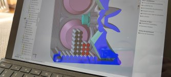
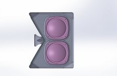
I was looking for a "compact" horn for another DIY BoomBox.
ABEC gave me nice directivity simulation, so, let's go !
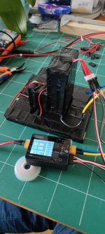
For now, the battery is done, I'll start the enclosure printing tomorrow.
I already made some boombox for friends, and this one is for me, so, as usual, it's a bit "too much"...!
For curious ones :
Outer dimensions : 200mm(w)x380mm(h)x300mm(d)
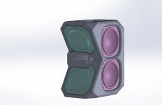
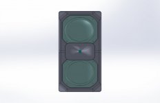
ATH dimensions : 140x80x80mm
LF :
2x 6" 18Sound 6ND430
1x IcePower A1000
80V constant voltage step-up
+/-12v constant voltage step-down
4x 6" SB Acoustics SB16PFC-00 (passive drivers)
HF :
1x 0.5" B&C DE5
1x Sure Electronics JAB3+ (mono version)
25V constant voltage step-up
Other :
Bluetooth 5.0 (on JAB3+)
DSP ADAU1701 (on JAB3+)
24v Li-Ion battery, 20Ah (6S6P, 3400mah cells), anti-spark switch, BMS with balancing.
I'll post more photos if you have some interest.
This little boom-box will sound very good... and loud !
Thanks.
(I'm acoustician and use CAD software everydays at work... and for my DIY projects...! But first time I work on horns.)
https://www.eighteensound.it/en/products/lf-driver/6-5/8/6ND430
https://icepoweraudio.com/buy/a-series/1000a/
https://sbacoustics.com/product/6-sb16pfc-00-paper/
https://www.bcspeakers.com/en/products/hf-driver/0-5/8/de5
https://store.sure-electronics.com/product/AA-JA31183
Hi Mabat, thank you to help me to run ATH scripts.
I was looking for a "compact" horn for another DIY BoomBox.
ABEC gave me nice directivity simulation, so, let's go !
For now, the battery is done, I'll start the enclosure printing tomorrow.
I already made some boombox for friends, and this one is for me, so, as usual, it's a bit "too much"...!
For curious ones :
Outer dimensions : 200mm(w)x380mm(h)x300mm(d)
ATH dimensions : 140x80x80mm
LF :
2x 6" 18Sound 6ND430
1x IcePower A1000
80V constant voltage step-up
+/-12v constant voltage step-down
4x 6" SB Acoustics SB16PFC-00 (passive drivers)
HF :
1x 0.5" B&C DE5
1x Sure Electronics JAB3+ (mono version)
25V constant voltage step-up
Other :
Bluetooth 5.0 (on JAB3+)
DSP ADAU1701 (on JAB3+)
24v Li-Ion battery, 20Ah (6S6P, 3400mah cells), anti-spark switch, BMS with balancing.
I'll post more photos if you have some interest.
This little boom-box will sound very good... and loud !
Thanks.
(I'm acoustician and use CAD software everydays at work... and for my DIY projects...! But first time I work on horns.)
https://www.eighteensound.it/en/products/lf-driver/6-5/8/6ND430
https://icepoweraudio.com/buy/a-series/1000a/
https://sbacoustics.com/product/6-sb16pfc-00-paper/
https://www.bcspeakers.com/en/products/hf-driver/0-5/8/de5
https://store.sure-electronics.com/product/AA-JA31183
Attachments
Last edited:
This is another of this tedious posts with questionable value. However, after I had complained about the strong diffraction effects on pattern, by the cabinet between 1 and 2k, I wanted to know if cabinet depth should be consindered for optimisation of diffraction effects. Not that I would for my box, the small size is essential, I just wanted to understand possible causes for what I was facing.
The result is, that a deeper cabinet had positive effects. The pattern at -6 dB is more even with a depth of 32 cm, as opposed to 27 cm (width in both cases 32 cm, heigth 57). At 32 cm, the aspect ratio is 1:1. Maybe a deep enclosure is even better. Without further interpretation, just the graphs.
Left: 27 cm, right: 32 cm (tweeter)
hor


ver dwn


ver up


hor


ver dwn


ver up


Left: 27 cm, right: 32 cm (woofer)
hor


ver up


ver dwn


Yes, I know, a lot of paper. Maybe someone wants to go follow this track ..
The result is, that a deeper cabinet had positive effects. The pattern at -6 dB is more even with a depth of 32 cm, as opposed to 27 cm (width in both cases 32 cm, heigth 57). At 32 cm, the aspect ratio is 1:1. Maybe a deep enclosure is even better. Without further interpretation, just the graphs.
Left: 27 cm, right: 32 cm (tweeter)
hor
ver dwn
ver up
hor
ver dwn
ver up
Left: 27 cm, right: 32 cm (woofer)
hor
ver up
ver dwn
Yes, I know, a lot of paper. Maybe someone wants to go follow this track ..
That's an interesting piece of work. I'm definitely curious about the result.I was looking for a "compact" horn for another DIY BoomBox.
ABEC gave me nice directivity simulation, so, let's go !
I did some thought experiments with simulations about this some time ago on another thread and came to conclusion that one can shift the effects seen on graphs around some by changing the box depth and roundovers but there is not too much else we can do with the back of the box than just make roundovers, smoothen the effects of the back of the enclosure. Everything is already quite chaotic at back edge of a box so we really cannot have too much control on there anymore and even if we had the sound is already attenuated we can't affect the total output much anymore. When the baffle is much smaller than the box side (depth) then there is some low frequencies that didn't diffract (that much) at the baffle edge yet and will diffract more at the back edge instead, and show some difference in the directivity graphs to shallower boxes. So there can be some useful changes in pattern with increased box depth but all the ripple you see stays, becauseThis is another of this tedious posts with questionable value. However, after I had complained about the strong diffraction effects on pattern, by the cabinet between 1 and 2k, I wanted to know if cabinet depth should be consindered for optimisation of diffraction effects. Not that I would for my box, the small size is essential, I just wanted to understand possible causes for what I was facing.
The result is, that a deeper cabinet had positive effects. The pattern at -6 dB is more even with a depth of 32 cm, as opposed to 27 cm (width in both cases 32 cm, heigth 57). At 32 cm, the aspect ratio is 1:1. Maybe a deep enclosure is even better. Without further interpretation, just the graphs.
Left: 27 cm, right: 32 cm (tweeter)
hor
View attachment 1050260 View attachment 1050256
ver dwn
View attachment 1050261 View attachment 1050257
ver up
View attachment 1050259 View attachment 1050258
hor
View attachment 1050266 View attachment 1050262
ver dwn
View attachment 1050265 View attachment 1050264
ver up
View attachment 1050267 View attachment 1050263
Left: 27 cm, right: 32 cm (woofer)
hor
View attachment 1050273 View attachment 1050269
ver up
View attachment 1050271 View attachment 1050270
ver dwn
View attachment 1050272 View attachment 1050268
Yes, I know, a lot of paper. Maybe someone wants to go follow this track ..
At high frequencies baffle edge works as sound source for the back edge and everything is already smeared and attenuated after the baffle edge diffraction so much so that what we see coming to the back edge and from the back edge diffraction just makes all kinds of small ripple to various directions. Sound from back edge seems to be at least 20db down (max +/-1db interference ripple).
To get completely rid of all the diffraction make the enclosure a sphere, or close enough approximation by rounding all edges. At least make sure the front side including baffle edge and all devices is made ripple free (diffraction free) before tackling the back, or do both at the same time. What happens on the front has far more effect on the graphs than anything that comes behind the enclosure. I would expect this is the same with audibility (I'm not sure how much audible any of this is). See the "ver dwn" graphs on both tweeter and woofer for example, all the main "features" of the response completely dominated what is on the front, first point of diffraction, and affected very little by changing the box depth. You cannot never fix the graph manipulating backside of the box so only thing you can do to really improve the graphs is by changing what is on the front.
Last edited:
Edit time over but I'll add that basically the first and only line of defense for speaker designer against interference due to the construct is using all the effort on the front, first places the sound interferes with, because after that it is just chaos and we've lost the control ") Treat the Baffle edge, roundover waveguide, think proximity of other transducers and constructs. We have to have some physical size to loudspeakers so the problem persist no matter what, sound interacts with the construct and shows at least some interference in frequency response plots. What is audible and what is good enough is the question to concentrate on, has to be somewhat practical as well In order to get "clean" measurements even with ideal transducers the output needs to be controlled with the construct so that after we lose the control the sound that would cause interference effect with direct sound has attenuated enough not to have severe effect on the response anymore, at least towards important direction like listening window. This seems to about happen with the box back edge diffraction, but the front edge very much affects the response. Easy solution would be a sphere as enclosure but we seem to prefer rectangular boxes more aesthetically.
Treat the Baffle edge, roundover waveguide, think proximity of other transducers and constructs. We have to have some physical size to loudspeakers so the problem persist no matter what, sound interacts with the construct and shows at least some interference in frequency response plots. What is audible and what is good enough is the question to concentrate on, has to be somewhat practical as well In order to get "clean" measurements even with ideal transducers the output needs to be controlled with the construct so that after we lose the control the sound that would cause interference effect with direct sound has attenuated enough not to have severe effect on the response anymore, at least towards important direction like listening window. This seems to about happen with the box back edge diffraction, but the front edge very much affects the response. Easy solution would be a sphere as enclosure but we seem to prefer rectangular boxes more aesthetically.
Treat the Baffle edge, roundover waveguide, think proximity of other transducers and constructs. We have to have some physical size to loudspeakers so the problem persist no matter what, sound interacts with the construct and shows at least some interference in frequency response plots. What is audible and what is good enough is the question to concentrate on, has to be somewhat practical as well In order to get "clean" measurements even with ideal transducers the output needs to be controlled with the construct so that after we lose the control the sound that would cause interference effect with direct sound has attenuated enough not to have severe effect on the response anymore, at least towards important direction like listening window. This seems to about happen with the box back edge diffraction, but the front edge very much affects the response. Easy solution would be a sphere as enclosure but we seem to prefer rectangular boxes more aesthetically.
Last edited:
Guys, check this out;
https://mesh2hrtf.sourceforge.io/#cover
a really good open-source university implementation of Burton-Miller collocation boundary element method coupled with the multi-level fast multipole method.
with py code as input-output.
with this code you can easily run 100.000 DOF (elements in ABEC language) on a desktop computer!
Basically all hard work has been done with the code, there is no difference between a hrtf or a horn calcualtion, just what you put in
Apart from the Export Mesh2HRTF routine, you can script almost any other operation in Blender and in this way hard code your pre-processing steps. For instance you could loop over several iterations with small changes in your setup or export parameters easily. For more information on scripting Blender, refer to the Blender documentation.
Cheers,
Kees
Last edited:
This is like a "find 10 differences" contest
It is easy to see in the line charts that these 5 cm of additional depth shifted the center frequency of diffraction by about minus 60 Herz and very slightly decreased the magnitude. Naturally, this is not a meaningful optimization, but some might want to go from here.
The line chart is in 5 degree increments.
I did a project using this last year, with (poor resolution) scanning of my own head using the flood illuminator sensor on the front of an iPhone.Guys, check this out;
https://mesh2hrtf.sourceforge.io/#cover
a really good open-source university implementation of Burton-Miller collocation boundary element method coupled with the multi-level fast multipole method.
with py code as input-output.
with this code you can easily run 100.000 DOF (elements in ABEC language) on a desktop computer!
Basically all hard work has been done with the code, there is no difference between a hrtf or a horn calcualtion, just what you put in
Apart from the Export Mesh2HRTF routine, you can script almost any other operation in Blender and in this way hard code your pre-processing steps. For instance you could loop over several iterations with small changes in your setup or export parameters easily. For more information on scripting Blender, refer to the Blender documentation.
Cheers,
Kees
It’s quite fast, and the addition of vibrating mesh elements with specified velocity conditions does make it possible to model a waveguide. However you’d need to modify the data writing method to create a source in SOFA format.
There’s lots of documentation for SOFA, so it does confuse me why it hasn’t seen more adoption for high-resolution loudspeaker 3D balloon data.
The Sourceforge pages have some handy tutorials:
https://sourceforge.net/p/mesh2hrtf/wiki/Tutorials/
The preprocessing scripts for refining of meshes before running the model might also be of interest:
https://github.com/Any2HRTF/PreProcessing
...and started to print the full scale (460 x 240 mm). This is a finished 1/4 of the mouth, just fitting on the bed. It's hollow to be filled (I don't know with what yet):I have a raw prototype scaled 1:2
Last edited:
This looks like a very nice tool ideed! I haven't heard about it.Guys, check this out;
https://mesh2hrtf.sourceforge.io/#cover
a really good open-source university implementation of Burton-Miller collocation boundary element method coupled with the multi-level fast multipole method.
with py code as input-output.
with this code you can easily run 100.000 DOF (elements in ABEC language) on a desktop computer!
Basically all hard work has been done with the code, there is no difference between a hrtf or a horn calcualtion, just what you put in
Apart from the Export Mesh2HRTF routine, you can script almost any other operation in Blender and in this way hard code your pre-processing steps. For instance you could loop over several iterations with small changes in your setup or export parameters easily. For more information on scripting Blender, refer to the Blender documentation.
Cheers,
Kees
- Home
- Loudspeakers
- Multi-Way
- Acoustic Horn Design – The Easy Way (Ath4)